Polystyrene foams incorporating nanographite and HFC-134

a polystyrene foam and nanographite technology, applied in the field of polystyrene foam, can solve the problems of reducing the insulative value of the foam, and potentially contributing to the global warming potential, and achieves less blowing agent, high r-value, and increased r-value of the foam board

Inactive Publication Date: 2008-10-02
OWENS CORNING INTELLECTUAL CAPITAL LLC
View PDF73 Cites 29 Cited by
  • Summary
  • Abstract
  • Description
  • Claims
  • Application Information

AI Technical Summary

Benefits of technology

[0019]It is an advantage of the present invention that the nanographite acts as a nucleating agent and eliminates the need to include a conventional nucleating agent such as talc.
[0020]It is yet another advantage of the present invention that the nanographite foams of the present invention increase the aged thermal resistance (R-values) of the foam boards.
[0021]It is also an advantage of the present invention that the inventive composition produces extruded foam products that have insulation values that are equal to or better than conventional extruded foam products produced with 1-chloro-1,1-difluoroethane (HCFC-142b).
[0022]It is another advantage of the present invention that extrude...

Problems solved by technology

On the other hand, a major disadvantage to these traditional blowing agents is that an increasing number of governments worldwide have mandated the elimination of CFC and HCFC blowing agents due to growing environmental concerns.
CFCs, and many other halocarbons, have come to be recognized as serious global environmental threats due to their ability to cause stratospheric ozone depletion and global warming.
Additionally, over time, the chlorofluorocarbon gas phase in the foam is released into the atmosphere,...

Method used


Image

  • Polystyrene foams incorporating nanographite and HFC-134
  • Polystyrene foams incorporating nanographite and HFC-134
  • Polystyrene foams incorporating nanographite and HFC-134

Examples


example 1

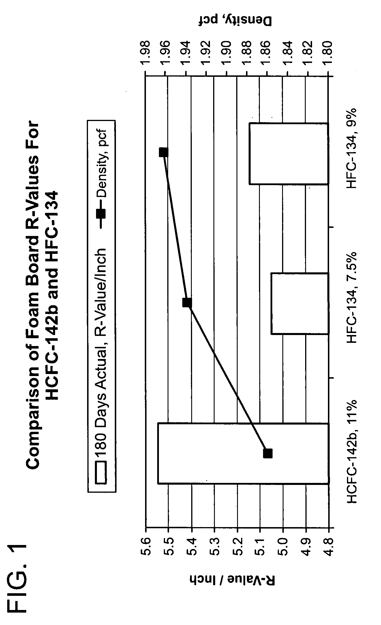
Comparison of Foam Board R-values For HCFC-142b and HFC-134 Containing No Nanographite

[0062]Compositions containing polystyrene, either 1,1,2,2-tetrafluoroethane (HFC-134) or 1-chloro-1,1-difluoroethane (HCFC-142b), and talc as depicted in Table 1 were formed according to the extrusion method described in detail above. In particular, the polystyrene and talc were heated to a melt mixing temperature of 150° C.-180° C. to form a melt polymer material. 1,1,2,2-tetrafluoroethane was then mixed into the polymer melt at a first pressure from 210-230 bars to generally disperse the blowing agent homogeneously in the melt polymer material and form a foamable gel. The foamable gel was then cooled to a temperature from 125° C.-135° C. The foamable gel was extruded in a twin screw extruder and through a die to a zone of reduced pressure (14.0 psi absolute-5.0 psi absolute) to produce the rigid foam boards. As used in the examples, the phrase “% by weight” is the % by dry weight of the component...

example 2

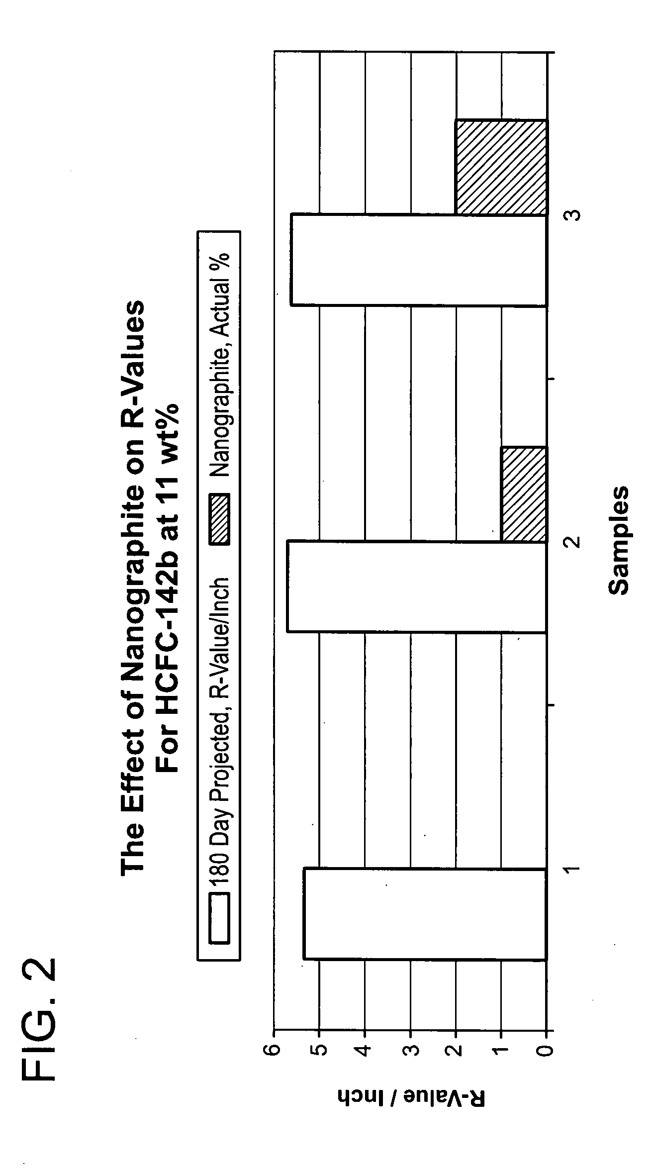
Effect of Nanographite on R-Values for Foamed Boards Formed with 11 wt % HCFC-142b

[0066]Compositions containing polystyrene, 1-chloro-1,1-difluoroethane (HCFC-142b), and nanographite as depicted in Table 4 were formed according to the extrusion method described in detail above. In particular, the polystyrene and nanographite were heated a melt mixing temperature of 150° C.-180° C. to form a melt polymer material. 1-chloro-1,1-difluoroethane was then mixed into the polymer melt at a first pressure from 210-230 bars to generally disperse the 1-chloro-1,1-difluoroethane homogeneously in the melt polymer material and form a foamable gel. The foamable gel was then cooled to a temperature from 125° C.-135° C. (the die melt temperature). The foamable gel was extruded in a twin screw extruder and through a die to a zone of reduced pressure (14.0 psi absolute-5.0 psi absolute) to produce the rigid foam boards. The process conditions are set forth in Table 4.

TABLE 4Compositions of Foamed Boar...

example 3

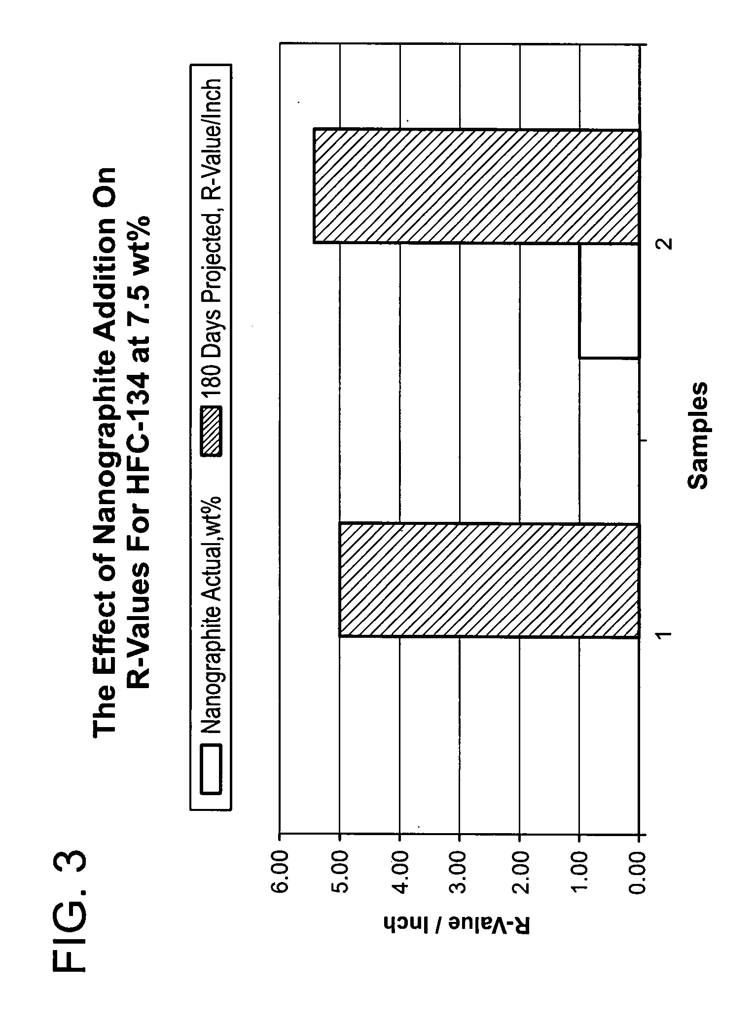
Effects of Nanographite on R-Values for Foamed Boards Formed with 7.5 wt % HFC-134

[0069]Compositions containing polystyrene, 1,1,2,2-tetrafluoroethane (HFC-134), and nanographite as depicted in Table 5 were formed according to the extrusion method described in detail above. In particular, the polystyrene and nanographite were heated a melt mixing temperature of 150° C.-180° C. to form a melt polymer material. 1,1,2,2-tetrafluoroethane (HFC-134) was then mixed into the polymer melt at a first pressure from 210-230 bars to generally disperse the 1,1,2,2-tetrafluoroethane homogeneously in the melt polymer material and form a foamable gel. The foamable gel was then cooled to a temperature from 125° C.-135° C. (the die melt temperature). The foamable gel was extruded in a twin screw extruder and through a die to a zone of reduced pressure (14.0 psi absolute-5.0 psi absolute) to produce the rigid foam boards. The process conditions are set forth in Table 6.

TABLE 6Compositions of Foamed Bo...


PUM

PropertyMeasurementUnit
Fractionaaaaaaaaaa
Fractionaaaaaaaaaa
Percent by massaaaaaaaaaa

Abstract

Polymeric foam and polymeric foam products that contain a foamable polymer material, nanographite, and 1,1,2,2-tetrafluoroethane (HFC-134) are provided. Preferably, the foamable polymer material is an alkenyl aromatic polymer material. The foam is free of other conventional blowing agents typically utilized in preparing a foamed product. The nanographite is not chemically or surface modified and is preferably compounded in a polyethylene methyl acrylate copolymer (EMA), which is used both as a medium and a carrier for the nanographite. The nanographite may be compounded in the polymer in an amount up to 60% loading. In addition, the nanographite acts as a nucleating agent, R-value enhancer, infrared attenuating agent, lubricant, UV absorber, and process aid. The inventive foam composition produces extruded foams that have R-values that are equal to or better than conventional extruded foams produced with 1-chloro-1,1-difluoroethane (HCFC-142b). The foamed products are desirably made by a conventional extrusion process.

Description

TECHNICAL FIELD AND INDUSTRIAL APPLICABILITY OF THE INVENTION[0001]The present invention relates generally to foam insulating products, and more particularly, to a polystyrene foam containing 1,1,2,2-tetrafluoroethane (HFC-134) and nanographite to increase insulating capability and decrease thermal conductivityBACKGROUND OF THE INVENTION[0002]Foamed resinous structures are useful in a wide variety of applications such as thermal insulation, as insulating structural members, in cushions, as packaging, and as adsorbents. The usefulness of rigid foamed polymeric boards in a variety of applications is well-known. For example, rigid polymeric foam boards are used as insulating structural members in many applications.[0003]Extruded foams are generally made by melting a polymer together with any desired additives-to create a polymer melt. A blowing agent is mixed with the polymer melt at an appropriate temperature and pressure to produce a foamable gel mixture. The foamable gel mixture is ...

Claims


Application Information

Patent Timeline
IPC IPC(8): C08J9/00C08F14/00
CPCB82Y30/00C08J9/0066C08J9/0071E04C2/205C08L9/02C08L9/06C08L25/06C08J9/146C08K3/04
Inventor DELAVIZ, YADOLLAHBREINDEL, RAYMOND M.WEEKLEY, MITCHELL Z.LOH, ROLAND R.CHOUDHARY, MANOJ K.
Owner OWENS CORNING INTELLECTUAL CAPITAL LLC
Why Eureka
Try Eureka