Photocatalyst Material Producing Method and Photocatalyst Material Producing Apparatus

Active Publication Date: 2008-10-16
TOSHIBA MITSUBISHI-ELECTRIC IND SYST CORP
View PDF13 Cites 13 Cited by
  • Summary
  • Abstract
  • Description
  • Claims
  • Application Information

AI Technical Summary

Benefits of technology

[0035]According to the photocatalyst material producing method and the photocatalyst material producing apparatus according to this invention, since a photocatalyst material film is produced by using high-field discharge, which is dielectric barrier discharge, in an atmosphere containing highly oxidative high-concentration ozone and oxygen atoms, a high-quality photocatalyst material that is uniform and thick and has no unevenness on its modified surface can be produced on the discharge surface, and the metho

Problems solved by technology

However, in any of these, it is difficult to increase the area of the photocatalyst material, to produce a large quantity of photocatalyst material, and to supply a photocatalyst material of stable quality.
Moreover, it is difficult to produce a p

Method used


Image

  • Photocatalyst Material Producing Method and Photocatalyst Material Producing Apparatus
  • Photocatalyst Material Producing Method and Photocatalyst Material Producing Apparatus
  • Photocatalyst Material Producing Method and Photocatalyst Material Producing Apparatus

Examples


embodiment 1

[0037]Embodiment 1 of this invention will be described with reference to FIG. 1 and FIGS. 3 to 10. In the drawings, the same reference numeral represents the same or equivalent part.

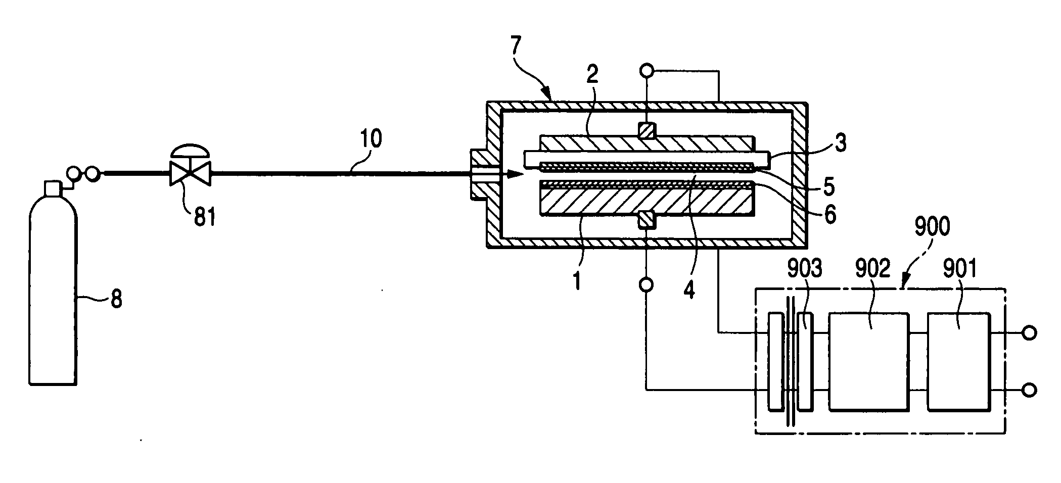
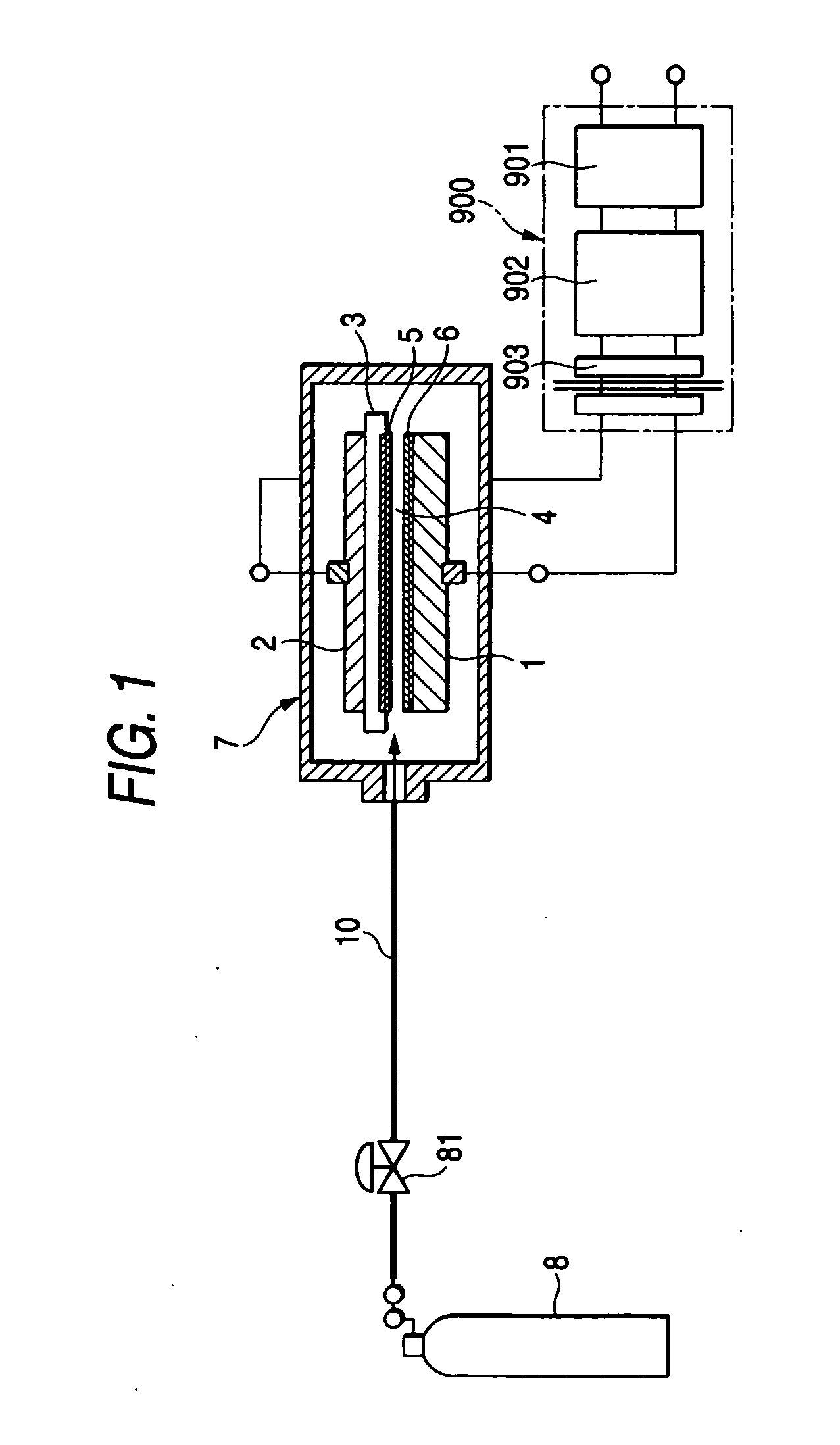
[0038]FIG. 1 is a structural block diagram for explaining a photocatalyst material producing method and apparatus according to Embodiment 1 of this invention. In FIG. 1, an oxidation starting material gas supply system that supplies oxygen (starting material gas) having a purity of 99.99% or higher includes a high-purity oxygen cylinder 8, an oxygen regulating valve 81 and the like, and fills a photocatalyst material producing unit 7 at a predetermined pressure. The photocatalyst producing unit 7 houses first and second electrodes 1, 2 forming a discharge zone with a discharge gap part 4 defined therein, and a dielectric material 3 arranged on the surface of the electrode 1 facing the electrode 2. Metals or compound materials 5, 6 to form a photocatalyst material film are fixed by coating or spraying to ...

embodiment 2

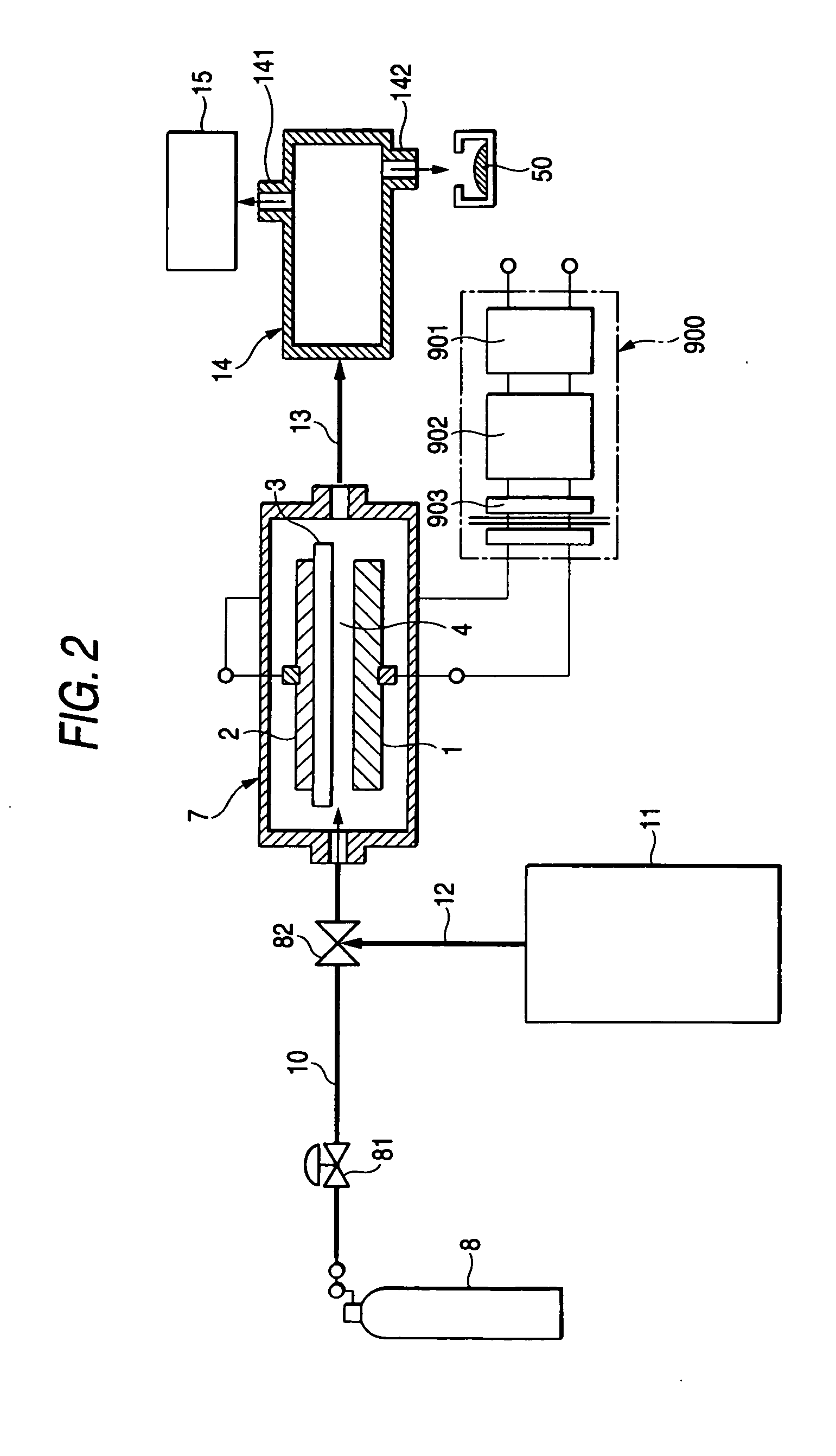
[0107]FIG. 2 is a structural block diagram for explaining a photocatalyst material producing method and apparatus according to Embodiment 2. In Embodiment 2, except for the construction parts and method specific to the following description, construction parts and method similar to the construction parts and method in the foregoing Embodiment 1 are provided and have the same effects.

[0108]In Embodiment 1, the mechanism and construction for producing a photocatalyst material film with respect to the surface of the electrode 1 or the surface of the dielectric material 3, which is the discharge surface of dielectric barrier discharge are mainly described. However, in Embodiment 2, metal powder, metal compound vapor or the like that can be a photocatalyst is mixed with oxidation gas to be supplied, and the gas is supplied to a dielectric barrier discharge unit, thereby modifying the metal powder or metal compound vapor to a photocatalyst material.

[0109]In FIG. 2, metal powder or metal c...

embodiment 3

[0112]FIG. 11 is a structural block diagram showing a photocatalyst material producing method and apparatus of multilayer discharge cell type according to Embodiment 3. In Embodiment 3, except for the construction parts and method specific to the following description, construction parts and method similar to the construction parts and method in the foregoing Embodiment 1 are provided and have the same effects.

[0113]In this Embodiment 3, plural electrode cells (for example, N−1 to N−8) are stacked and dielectric barrier discharge is evenly generated in discharge gaps 4 provided in parallel in the respective cells, thereby enabling production of photocatalyst material films on plural electrode surface and dielectric surfaces at a time.

[0114]In FIG. 11, a base 600 for stacking discharge cells thereon and a chamber 700 form a gas space, and oxygen gas is supplied from an oxygen gas inlet 89, thereby filling the gas space with oxygen gas. Also, flat plate-like low-voltage electrode 1, i...


PUM

PropertyMeasurementUnit
Fractionaaaaaaaaaa
Frequencyaaaaaaaaaa
Energyaaaaaaaaaa

Abstract

This invention provides a new photocatalyst material producing apparatus and photocatalyst material producing method that can produce a large quantity of photocatalyst material of high quality by a chemical reaction in light high-field plasma in a highly oxidative high-concentration ozone medium state, instead of systems to produce a photocatalyst material by PVD and CVD, which are conventional dry deposition methods.
In a photocatalyst material producing method and photocatalyst material producing apparatus according to this invention, a pair of facing electrodes are provided via a dielectric material in a discharge gap where gas mainly containing oxygen gas is supplied, and an AC voltage is applied between the electrodes to generate dielectric barrier discharge (silent discharge or creeping discharge) in the discharge gap. Thus, oxygen gas containing ozone gas is created and a metal or metal compound is modified to a photocatalyst material by the dielectric barrier discharge.

Description

TECHNICAL FIELD[0001]This invention relates to a photocatalyst material producing method and a photocatalyst material producing apparatus for producing a photocatalyst material of high quality.BACKGROUND ART[0002]Photocatalyst materials are particularly excellent in their substance decomposition ability and ultra-hydrophilicity function. Utilizing such function, photocatalyst materials are used for air purification, water purification, decomposition of organic substances, and anti-fogging and anti-soiling coating material.[0003]Methods and apparatuses for producing such photocatalyst materials are classified into two types: dry deposition methods and wet deposition methods.[0004]As dry deposition methods, there are PVD (physical vapor deposition) and CVD (chemical vapor deposition). As photocatalyst producing methods based on PVD, there have been Patent References 1 and 2. As photocatalyst producing methods based on CVD, there have been Patent References 3 and 4 and the like.[0005]A...

Claims


Application Information

Patent Timeline
IPC IPC(8): B05B5/025B05D3/06
CPCB01J23/02B01J23/06B01J23/08B01J23/14B01J23/16B01J37/349B01J23/745B01J35/004C01B13/11C01B2201/64B01J37/0238B01J23/72
Inventor TABATA, YOICHIROSAITSU, TETSUYAOKIHARA, YUJIROUEDA, RYOHEI
Owner TOSHIBA MITSUBISHI-ELECTRIC IND SYST CORP
Why Eureka
Try Eureka