
Method to protect the magnetic recording head from thermal asperities during disk drive operation

a technology of thermal asperities and magnetic recording heads, which is applied in the direction of maintaining head carrier alignment, manufacturing tools, instruments, etc., can solve the problems of increased the chance of head-disk contact, and failure of the drive, so as to achieve easy interfaces and implements.

Active Publication Date: 2008-10-16
SAE MAGNETICS (HK) LTD
View PDF22 Cites 6 Cited by
  • Summary
  • Abstract
  • Description
  • Claims
  • Application Information

AI Technical Summary

Benefits of technology

[0020]A second object of the present invention is to provide such a method that is efficient, easy to implement within present manufacturing practices and inexpensive.
[0021]A third object of the present invention is to provide such a method that easily interfaces with present process steps and does not require more stringent attention to manufacturing tolerances.
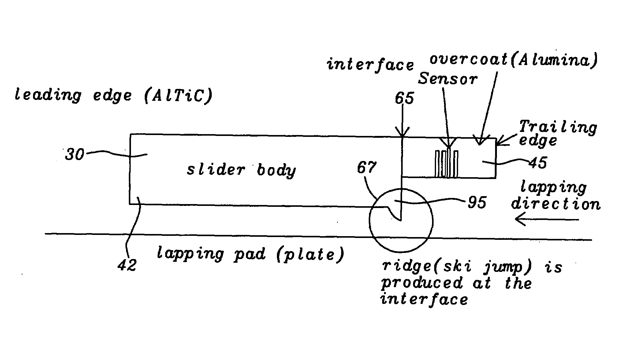
[0023]These objects are all achieved by a CMP (chemical mechanical process) lapping of the slider using a chemical slurry enhanced by the addition of chemicals such as KOH or other strong basic compounds. The lapping process creates a microtexture on the slider body by selectively etching the alumina over the titanium carbide. As a result of the lapping process a single ridge of uniform height and consistent shape is formed on the ABS of the slider at the line of its intersection with the interfacial plane between the AlTiC portion of the slider substrate and the alumina-encapsulated read / write head. The shape and location of this ridge is such that it will protect the read / write head from thermal asperities caused by head-disk interactions during HDD operation. Since this ridge performs a similar task as analogous structures formed by other prior art methods, yet since it does not require the formation of such additional structures or the introduction of foreign materials or additional or new process steps as do the other prior art methods, it is believed that this is a highly, efficient and cost-effective method.

Problems solved by technology

Such a modulation can progress to a head-disk contact, damaging the head or disk or both and, if severe enough, causing a failure of the drive.
Other reasons for variations in the magnetic spacing are such internal problems as variation in disk smoothness, surface contamination, stiction, or high-altitude drive operation.
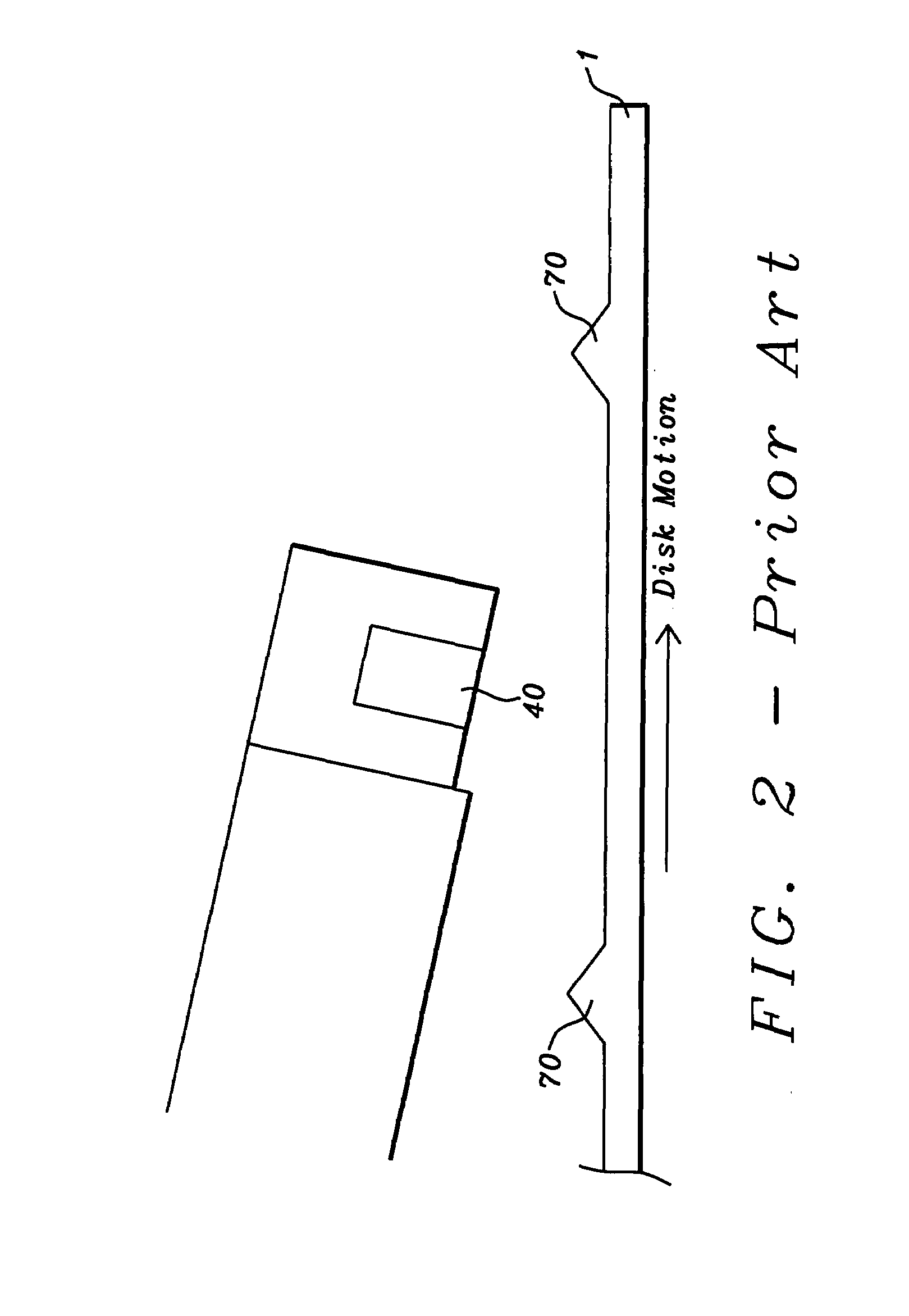
Another major problem that results from magnetic spacing variations during disk drive operation is thermal “asperities,” variations in read head operation that result from its deviations from thermal equilibrium.
Even some of the next generation technologies, such as dynamic write excitation during the write operation of the disk drive, create a head-disk contact problem.
By exciting the writer, we intentionally cause the transducer to protrude, reducing the magnetic spacing and thus increasing the chance of head-disk contact.
While this certainly addresses the problem, the amount of recession suggested, approximately 40 nm, is very large and will reduce the efficiency of the head.
Also, this type of solution requires very tight process control in creating the recession, and such process control is a constant challenge in manufacturing.
Another potential problem associated with this approach is due to the nature of the hardness variations of the writer and reader materials, which would cause localized profile variations that would adversely affect the head operation.
This does help to reduce the effects caused by a head-disk contact, but it requires a multiplicity of complicated process steps and, therefore, lowers the manufacturing efficiency.
All of these ideas suggest the necessity of additional process steps to build protective features into the head, thereby increasing the cost of manufacturing.
This approach, therefore, also warrants additional processing steps and masks which, in turn, increase manufacturing costs.
This approach runs the risk of allowing metallic elements in the transducers to corrode, since they lack the necessary protection of a coating.
With the next generation of metals being considered for use in head fabrication, the potential for corrosion is even increased.
All of these inventions require additional process steps which raise the manufacturing cost of the slider.

Method used


Image

  • Method to protect the magnetic recording head from thermal asperities during disk drive operation
  • Method to protect the magnetic recording head from thermal asperities during disk drive operation
  • Method to protect the magnetic recording head from thermal asperities during disk drive operation

Examples


Embodiment Construction

[0036]The preferred embodiment of the present invention teaches a method of chemical / mechanical (CMP) polishing the ABS of a slider, using a colloidal silica slurry or a silica slurry enhanced by the addition of KOH or other strong bases, so that a ridge is produced on the ABS plane of the slider substrate at its line of intersection with the interfacial plane between the slider body and the read / write head. For a given slurry composition, the ridge has a consistent height and shape and serves to protect the read / write head from thermal asperities during HDD operation.

[0037]Referring again to FIG. 4, as was discussed above, this figure schematically represents the results of the present invention. A lapping process uses an abrasive slurry of colloidal silica to which is added an amount of KOH. The lapping is applied in the direction from the trailing edge of the read / write head (45), towards the leading edge of the slider substrate (30). The result is a smooth ski jump shaped ridge ...


PUM

PropertyMeasurementUnit
Fractionaaaaaaaaaa
Fractionaaaaaaaaaa
Volumeaaaaaaaaaa

Abstract

A slider mounted read / write head is protected from thermal asperities due to head-disk interactions by a ridge formed along an interfacial plane that extends above the ABS plane of the slider. The ridge is formed as part of a lapping process that is directed from the read / write head towards the slider substrate and uses an abrasive slurry to which may be added a strong base such as KOH. The height of the ridge is less than approximately 2 nm.

Description

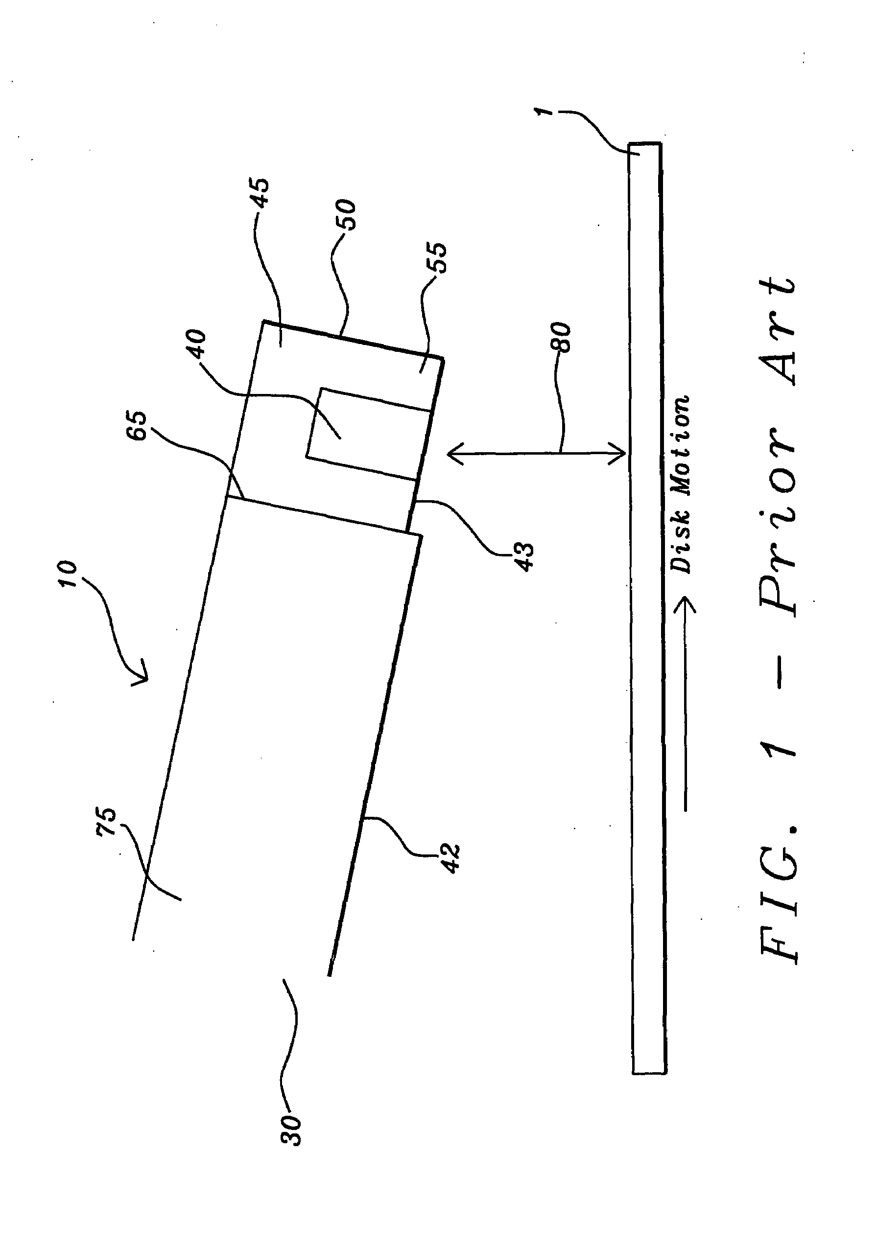
BACKGROUND OF THE INVENTION[0001]1. Field of the Invention[0002]This invention relates to the fabrication of thin film magnetic read / write heads and particularly to a method for forming a slider surface so that the read / write head is less subject to thermal asperities due to near contact with a magnetic disk.[0003]2. Description of the Related Art[0004]As shown in FIG. 1, a hard disk drive (HDD) uses an encapsulated, small thin film magnetic read / write head (40), formed on a ceramic substrate (45) to read and write data on a magnetic medium or storage disk (1). The read / write head is formed using well known semiconductor deposition techniques such as electroplating, CVD (chemical vapor deposition) and photolithographic patterning and etching. The entire structure of head plus substrate is called a slider (10). FIG. 1 is a schematic illustration of such a device as is used in the prior art and whose performance improvement is the object of the present invention. The slider (10) has a...

Claims


Application Information

Patent Timeline
IPC IPC(8): G11B5/10
CPCG11B5/102G11B5/3106Y10T29/49041G11B5/40G11B5/3169
Inventor MAHDEV, NIRAJYASUDA, KASUMAZACHA, ELLIS
Owner SAE MAGNETICS (HK) LTD
Learn More