

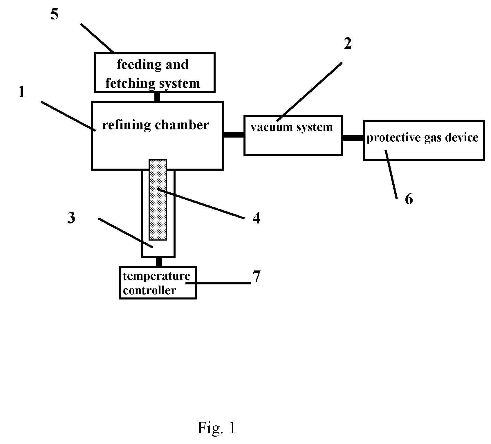
High Vacuum In-Situ Refining Method for High-Purity Materials and an Apparatus Thereof
- Summary
- Abstract
- Description
- Claims
- Application Information
AI Technical Summary
Benefits of technology
Problems solved by technology
Method used
Image

Examples
example 1
A High Vacuum In-situ Refining Method for High-purity Metal Magnesium by Two Steps
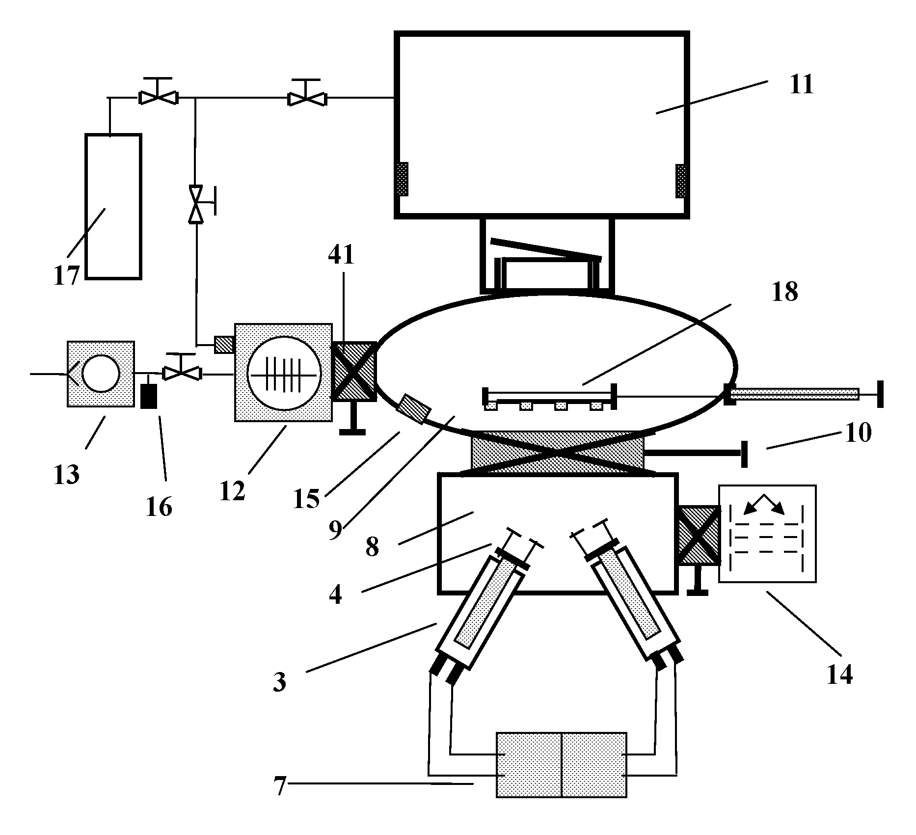
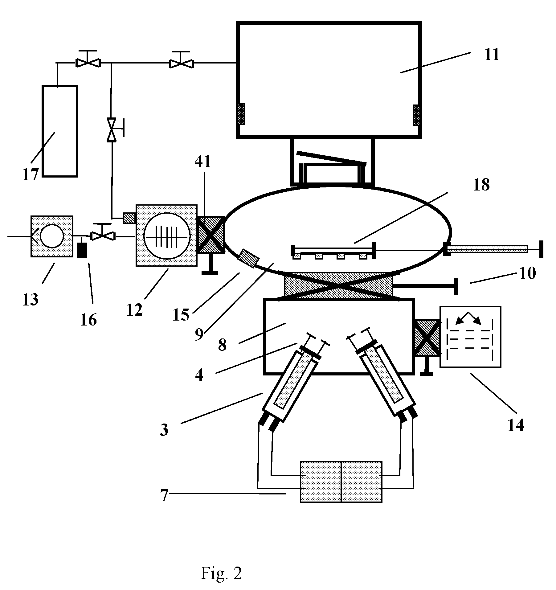
[0047]In the process flow diagram according to the present invention as shown in FIG. 1, the specific steps of refining high-purity metal magnesium by using the high vacuum in-situ refining method by two steps are as follows:
[0048]1) Fill high-purity argon gas in the high vacuum in-situ refining device as protective gas for purification of metal magnesium;
[0049]2) The crucible shown in FIG. 5 is composed of the upper and lower part 34, 35, which respectively correspond to the upper and the lower heating wire 28, 29 of the diffusion furnace shown in FIG. 4. That is, the upper part 38 of the crucible is heated by the upper heating wire 28 of diffusion furnace, while the lower part 39 of the crucible is heated by the lower heating wire 29 of the diffusion furnace 28. Suitable amount of rough-purity metal magnesium (99.95%) can be put in the crucible to fill the lower part 39 exactly;
[0050]3) Put the cruci...
example 3
High Vacuum in-situ Refining Method for High-purity Sodium Hydroxide by Two Steps
[0071]In the process flow diagram according to the present invention as shown in FIG. 1, the specific steps of refining high-purity sodium hydroxide by the use of high vacuum in-situ refining method by two steps are as follows:
[0072]1) Fill high-purity argon gas in high vacuum in-situ refining device as protective gas for purification of sodium hydroxide;
[0073]2) The crucible shown in FIG. 4 is composed of the upper and lower parts 34, 35, which respectively correspond to the upper and lower heating wires 28, 29 of the diffusion furnace shown in FIG. 4. That is, the upper part 38 of the crucible is heated by the upper heating wire 28 of the diffusion furnace, while the lower part 39 of the crucible is heated by the lower heating wire 29 of the diffusion furnace. Suitable amount of rough-purity sodium hydroxide (99.7%) can be put in the crucible to fill the lower part 39 exactly;
[0074]3) Put the crucible...
PUM
| Property | Measurement | Unit |
|---|---|---|
| Fraction | aaaaa | aaaaa |
| Pressure | aaaaa | aaaaa |
| Fraction | aaaaa | aaaaa |
Abstract
Description
Claims
Application Information