Power plant and fuel supply method therefor
a technology for power plants and fuel supply devices, which is applied in the direction of machines/engines, combustion air/fuel air treatment, electric control, etc., can solve the problems of increasing unburnt hc (hydrocarbons) and pm (particle materials), and the inability to reform all fuel components, so as to achieve suppressed undesired fuel flow on the walls and high boiling point
- Summary
- Abstract
- Description
- Claims
- Application Information
AI Technical Summary
Benefits of technology
Problems solved by technology
Method used
Image
Examples
first embodiment
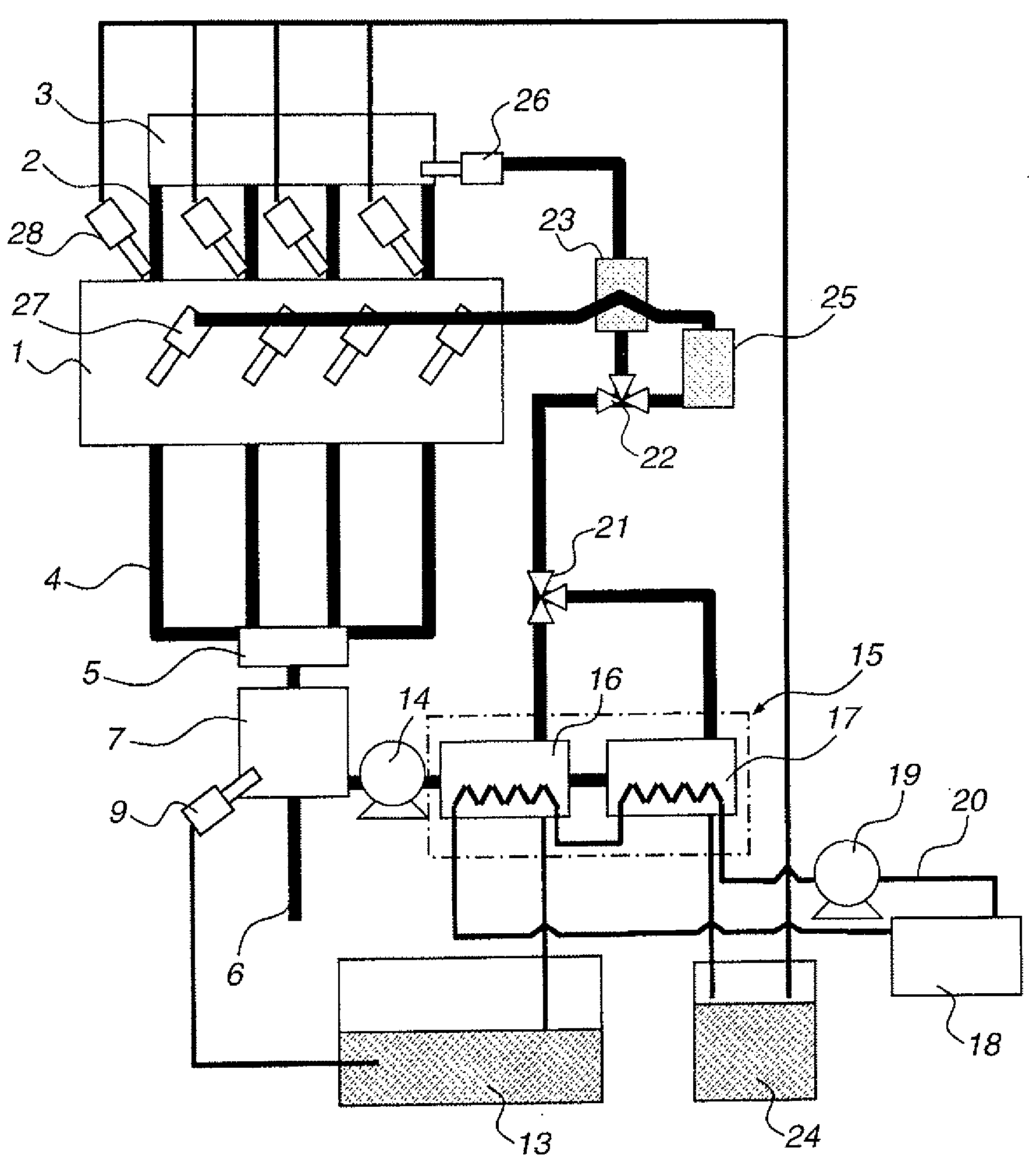
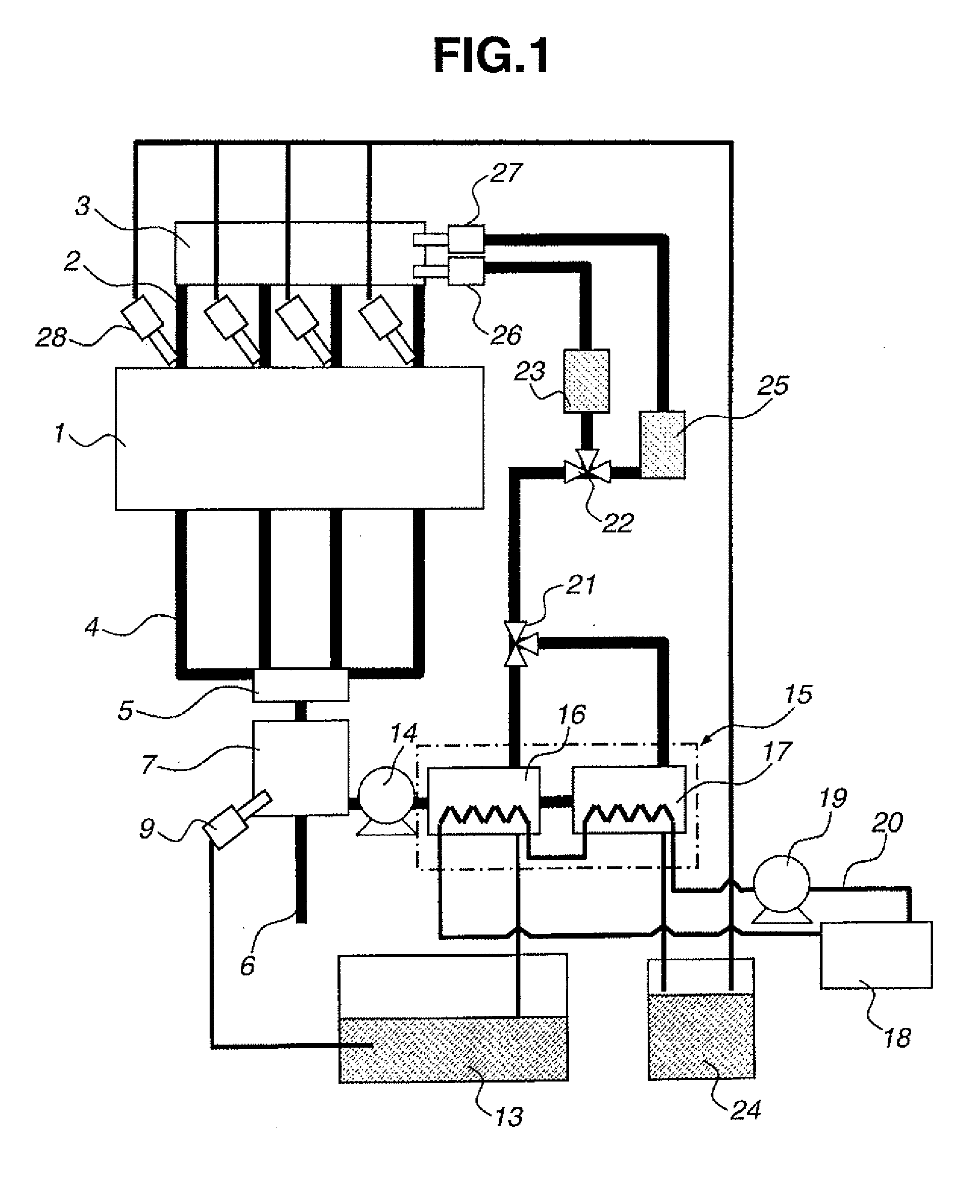
[0024]FIG. 1 is a block diagram showing a power plant of the present invention. In FIG. 1, an engine 1 is connected to an intake collector 3 through an intake manifold 2. An exhaust purifying catalyst 5 is connected to a branch joined portion of an exhaust manifold 4 of engine 1. Around an exhaust pipe 6 that extends downward from the catalyst, there is mounted a fuel conversion device 7 that converts a supplied liquid fuel to an evaporated fuel and a reformed fuel by practically using waste heat of the internal combustion engine as energy, such as waste heat from exhaust pipe 6.
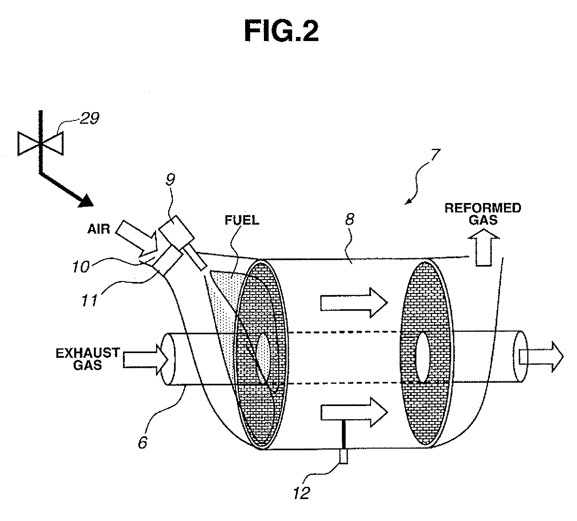
[0025]Details of fuel conversion device 7 are shown in FIG. 2. In fuel conversion device 7, there is formed a cylindrical space that surrounds exhaust pipe 6, and in the space, there is arranged a reforming catalyst 8 that includes a honeycomb cordierite bed coated with platinum catalyst. At an inlet side of reforming catalyst 8, there is provided an air intake opening 10 through which air can enter device 7...
second embodiment
[0067]FIGS. 11 and 12 show fuel supply control maps provided in accordance with an operation condition of the
[0068]In the second embodiment, like in the first embodiment, a low octane fuel with a high boiling point is fed to engine 1 after being changed to an evaporated fuel, and thus, even when a fuel having a high boiling point, like light oil or the like, is used, undesirable fuel flow on walls of the intake port and combustion chamber is suppressed or at least minimized. Furthermore, only when the engine is under a low load operation condition, the reformed gaseous fuel is fed to auxiliary combustion chamber 41 to produce jetted flame through nozzle holes 42 the for burning the mixture of the evaporated fuel and air in main combustion chamber 35. Accordingly, the combustion stability of the mixture in combustion chamber 35 under the low load operation condition is much improved as compared with that of the above-mentioned first embodiment. Thus, the lean limit for stable combust...
PUM
 Abstract
Description
Claims
Application Information
 - R&D
- Intellectual Property
- Life Sciences
- Materials
- Tech Scout
- Unparalleled Data Quality
- Higher Quality Content
- 60% Fewer Hallucinations
Browse by: Latest US Patents, China's latest patents, Technical Efficacy Thesaurus, Application Domain, Technology Topic, Popular Technical Reports.
© 2025 PatSnap. All rights reserved.Legal|Privacy policy|Modern Slavery Act Transparency Statement|Sitemap|About US| Contact US: help@patsnap.com


