Method for Producing Paraxylene Comprising an Adsortion Step and Two Isomerization Steps

a technology of paraxylene and isomerization step, which is applied in the direction of separation process, organic chemistry, chemistry apparatus and processes, etc., can solve the problems of high installation and operation cost of the distillation column for separating the two streams, and the purity of the obtained para-xylene is not good,

Active Publication Date: 2008-10-23
INST FR DU PETROLE
View PDF11 Cites 37 Cited by
  • Summary
  • Abstract
  • Description
  • Claims
  • Application Information

AI Technical Summary

Benefits of technology

[0017]Thus, the present invention retains the advantages of using two distinct isomerization steps by carrying out these isomerizations on two raffinates, which overcomes the disadvantage of a very expensive distillation column.

Problems solved by technology

However, the disadvantage of the process described in FR-A-2 792 632 resides in the fact that the distillation column for separating the two streams is very expensive both to install and to operate.
Those documents describe the withdrawal of two distinct raffinates from a simulated moving bed adsorption column, but have limitations either as regards the purity of the para-xylene obtained, or as regards the yield of para-xylene, linked to the co-production of other isomers.

Method used


Image

  • Method for Producing Paraxylene Comprising an Adsortion Step and Two Isomerization Steps
  • Method for Producing Paraxylene Comprising an Adsortion Step and Two Isomerization Steps
  • Method for Producing Paraxylene Comprising an Adsortion Step and Two Isomerization Steps

Examples


example 1

Comparative

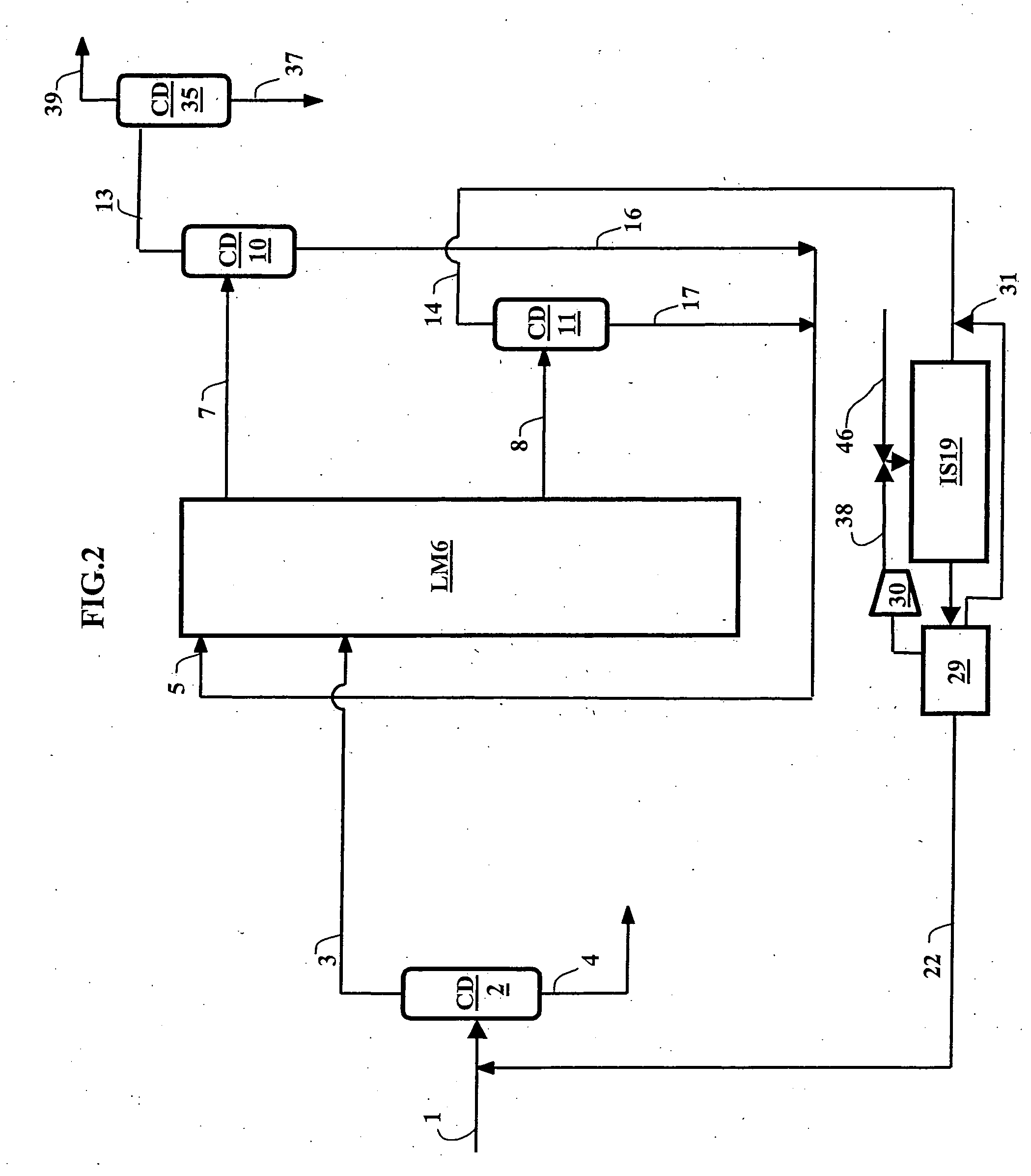
[0114]This example illustrates the prior art and describes an aromatic loop shown in FIG. 2 and comprising:[0115]a xylenes column (CD2) for extracting C9 and C10 aromatics (stream 4) and sending a stream (3) essentially constituted by C8 aromatics to the adsorption unit (LM6);[0116]a simulated moving bed adsorption unit (LM6) with 4 zones from which an extract (7) and a single raffinate (8) are withdrawn;[0117]an isomerization unit (IS19) supplied by a portion (14) of the raffinate (8) after elimination of desorbant by means of the distillation column (CD11);[0118]a para-xylene purification column (CD35) located downstream of the distillation column (CD10). Para-xylene (stream 37) with a purity of more than 99.7% is withdrawn from the bottom of said column (CD35).

[0119]The unit employed for the flow rate was the kilotonne per year (kt / yr).

[0120]The feed (1) which supplied the aromatic loop was derived from reforming and had a flow rate of 460 kt / yr. 1540 kt / yr of isomerat...

example 2

In Accordance with the Invention

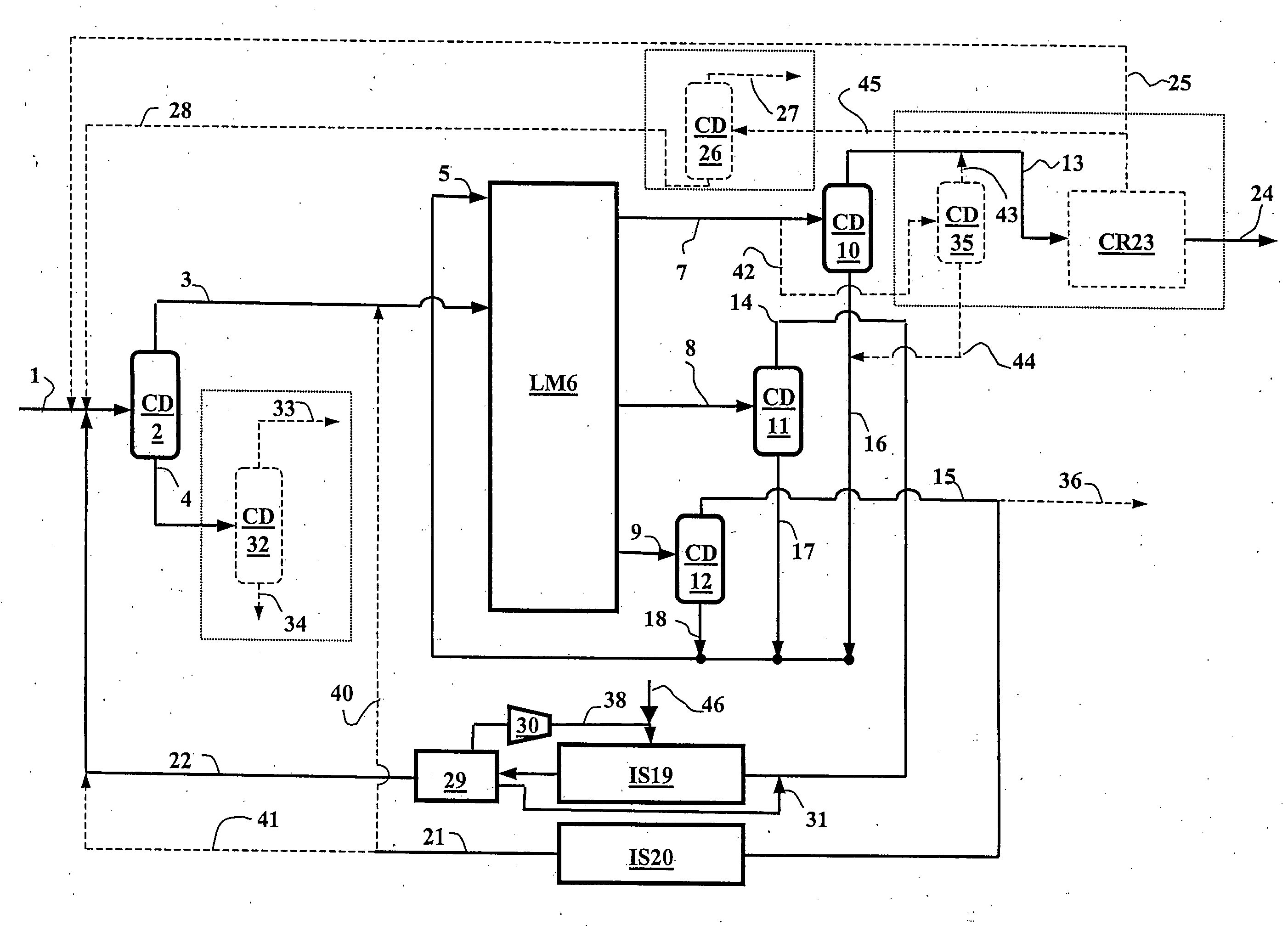
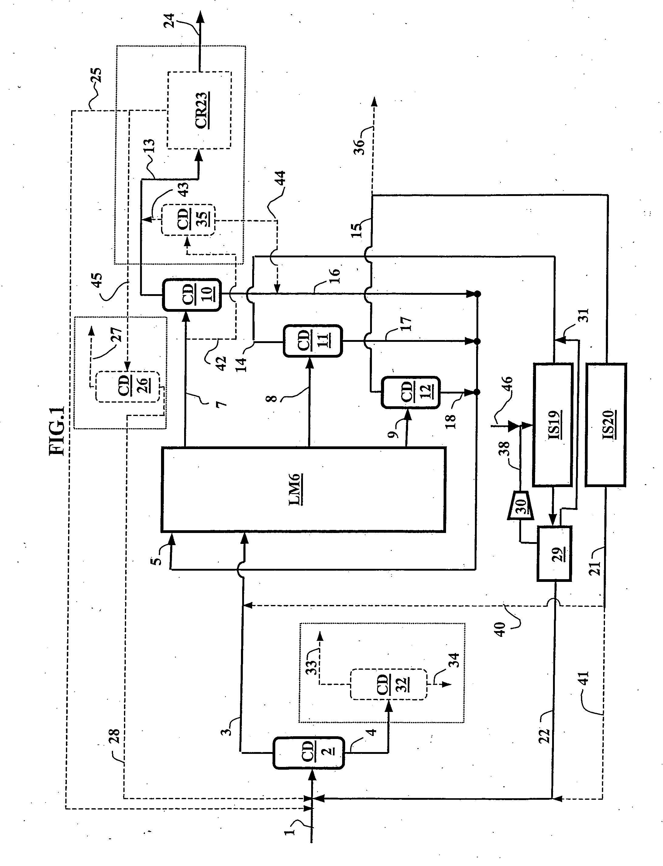
[0143]This example illustrates an application of the invention consisting of increasing the capacity of the aromatic loop described in Example 1 by 30%. This example is illustrated in FIG. 1 of the invention.

[0144]The simulated moving bed separation unit (LM6) is adapted to function with a new stream, termed 2-raffinate, namely to give five principal streams (desorbant, feed, extract, intermediate raffinate and 2-raffinate).

[0145]The four-stream adsorption unit (LM6) of Example 1 of the prior art was thus modified to be able to incorporate this fifth stream, either by adding one on-off valve per bed, the set of valves being connected to a common collector, or by modifying the rotary valve to manage five principal streams.

[0146]Generally, the mechanical strength of the distributor plates separating the beds is sufficient to accept an increase of the order of 30% in the internal flow rate. If this were not the case, the sieve would have to be discharged...


PUM

PropertyMeasurementUnit
pressureaaaaaaaaaa
temperatureaaaaaaaaaa
pressureaaaaaaaaaa

Abstract

A process for producing para-xylene from a hydrocarbon feed is described in which an adsorption column operating as a simulated moving bed with at least five zones delivers an extract, a 2-raffinate and an intermediate raffinate.The extract is distilled and the distillate is optionally re-crystallized to recover para-xylene with a purity of at least 99.7%. The 2-raffmate is distilled then isomerized in a reactor preferably operating in the liquid phase and at a low temperature. The intermediate raffinate with an enriched ethylbenzene content is distilled then isomerized in the vapour phase.

Description

FIELD OF THE INVENTION[0001]Para-xylene production has been increasing steadily for thirty years at a mean annual rate of 5% to 6%. Para-xylene is used to produce terephthalic acid and polyethylene terephthalate resins for synthetic textiles, audio and video cassettes, bottles and, more generally, plastic materials.[0002]To satisfy the ever-increasing demand for para-xylene, petrochemists can choose between increasing the capacity of existing units or constructing new units, which will necessarily be larger as the break-even point for such units is about 400000 tonnes / year.[0003]The present invention can satisfy these two cases and accommodate an increase in the capacity of existing units (usually termed debottlenecking) as the modifications involved are relatively modest.[0004]All of the equipment in an existing production unit may be re-used, the additions consisting of 1) one on-off valve per bed or a modified rotary valve in the adsorption section of the simulated moving bed sep...

Claims


Application Information

Patent Timeline
Patent Type & Authority Applications(United States)
IPC IPC(8): C07C15/08C07C5/27C07C7/12C07C7/13
CPCC07C5/2737C07C5/2775C07C7/12C07C15/08B01D15/1821C07C7/13
Inventor LEFLAIVE, PHILIBERTWOLFF, LUCHOTIER, GERARD
Owner INST FR DU PETROLE
Why Eureka
Try Eureka