Signal Processing Circuit Comprising Ion Sensitive Field Effect Transistor and Method of Monitoring a Property of a Fluid

Active Publication Date: 2008-10-30
DNAE GRP HLDG
View PDF9 Cites 104 Cited by
  • Summary
  • Abstract
  • Description
  • Claims
  • Application Information

AI Technical Summary

Benefits of technology

[0031]configuring an ion sensitive field effect transistor to operate as a switch of a

Problems solved by technology

It has also been shown that even conventional pH-ISFETs with unmodified Si3N4 membranes exhibit a limited but measurable sensitivity to K+ and Na+ ions.
Secondly, processing power must be provided to perform the correction.
Thirdly, the process of c

Method used


Image

  • Signal Processing Circuit Comprising Ion Sensitive Field Effect Transistor and Method of Monitoring a Property of a Fluid
  • Signal Processing Circuit Comprising Ion Sensitive Field Effect Transistor and Method of Monitoring a Property of a Fluid
  • Signal Processing Circuit Comprising Ion Sensitive Field Effect Transistor and Method of Monitoring a Property of a Fluid

Examples


Embodiment Construction

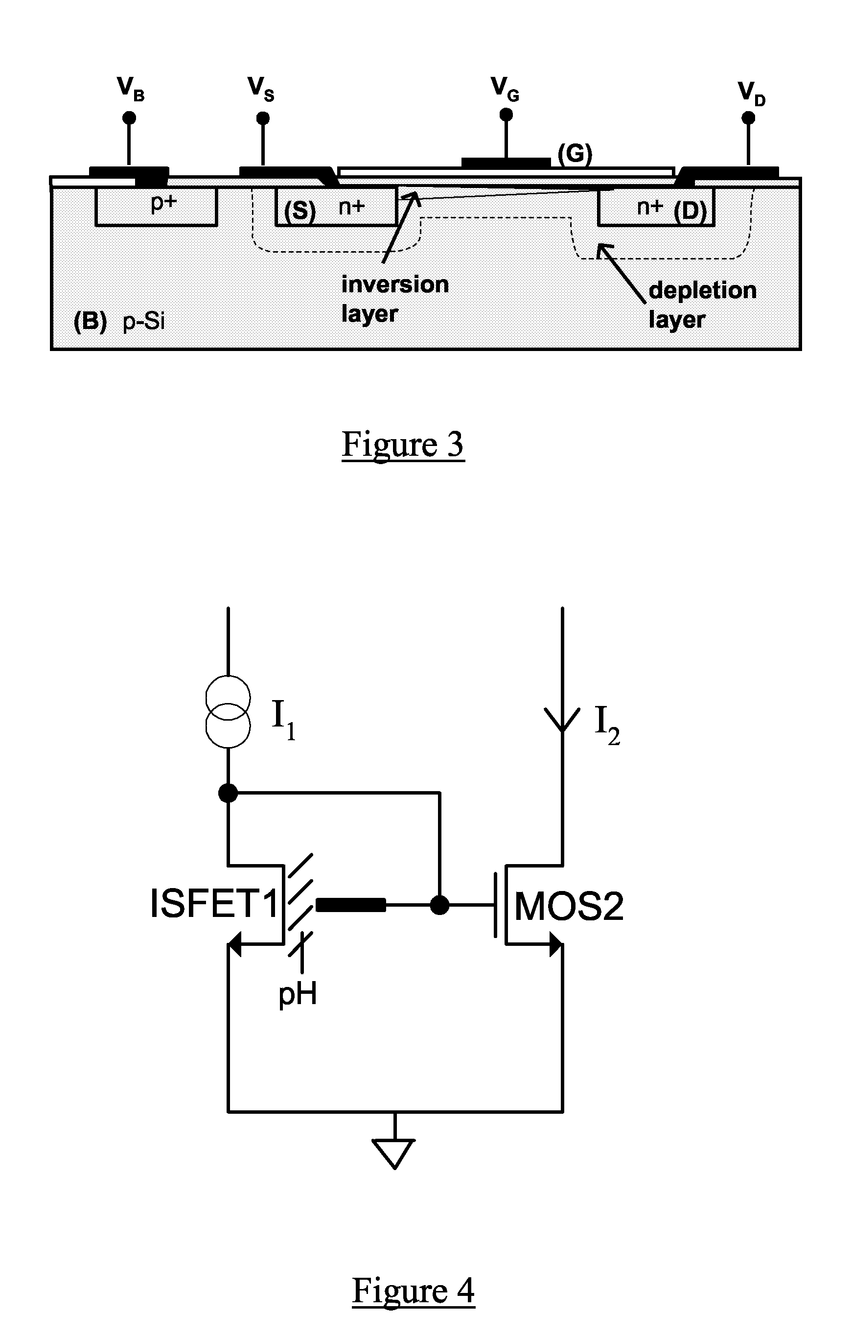
[0045]An n-channel FET such as that illustrated in FIG. 3 is a four terminal device, consisting of a p-type silicon substrate (B) and two highly-doped n-type wells known as the source (S) and the drain (D). The silicon surface is covered with a silicon dioxide insulator. A polysilicon gate contact (G) controls the charge within the region under the insulator surface between source and drain, known as the channel.

[0046]As the voltage VG applied to the gate is increased, positive charge is initially repelled from the channel forming a depletion layer with no mobile charge carriers and a net negative charge. As the gate voltage is further increased, this depletion layer widens until electrons begin to be drawn from source and drain into the channel, forming an inversion layer. The transistor is usually operated above a certain threshold voltage for which the channel is strongly inverted and the mobile electrons in the inversion layer drift across the channel when a potential difference...


PUM


Abstract

A signal processing circuit comprising one or more ion sensitive field effect transistors, ISFETs, and a biasing circuit for biasing the or each ion sensitive field effect transistor to operate in the weak inversion region.

Description

FIELD OF THE INVENTION[0001]The present invention relates to ion sensitive field effect transistors and to processing and control systems utilising ion sensitive field effect transistors.BACKGROUND TO THE INVENTION[0002]The ion-sensitive field effect transistor (ISFET) is based on a MOSFET with a remote gate (or “reference electrode”) lying beneath a chemically-sensitive insulator. The surface of the insulator is exposed to an electrolyte upon which measurements are to be made. A typical ISFET use scenario is illustrated in FIG. 1. Field effects from ionic charge interaction at the insulator surface cause shifts in the ISFET drain current vs gate to source voltage (ID-VGS) characteristic as illustrated in FIG. 2. The insulator in contact with the electrolyte is chosen according to its chemical properties and sensitivity to a particular ion.[0003]For ISFETs designed to measure the pH of an electrolyte, i.e. the H+ ion content of the electrolyte, silicon nitride and aluminium oxide me...

Claims


Application Information

Patent Timeline
IPC IPC(8): H01L25/00G01N27/26G01N27/62G01N27/414
CPCG01N27/4148H01L2924/0002H01L2924/00G01N27/4145G01N27/414
Inventor TOUMAZOU, CHRISTOFERPREMANODE, BHUSANASHEPHERD, LEILA
Owner DNAE GRP HLDG
Why Eureka
Try Eureka