
Method for characterizing transparent thin-films using differential optical sectioning interference microscopy

a technology of differential optical sectioning and interference microscopy, which is applied in the field of transparent thin films, can solve the problems that the simultaneous measurement of n and d of inhomogeneous thin films cannot be achieved, and achieve the effect of simple setup, easy construction and calibration

Inactive Publication Date: 2008-10-30
ACAD SINIC
View PDF1 Cites 15 Cited by
  • Summary
  • Abstract
  • Description
  • Claims
  • Application Information

AI Technical Summary

Benefits of technology

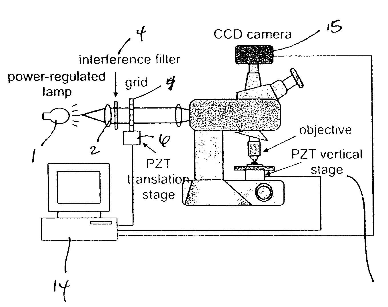
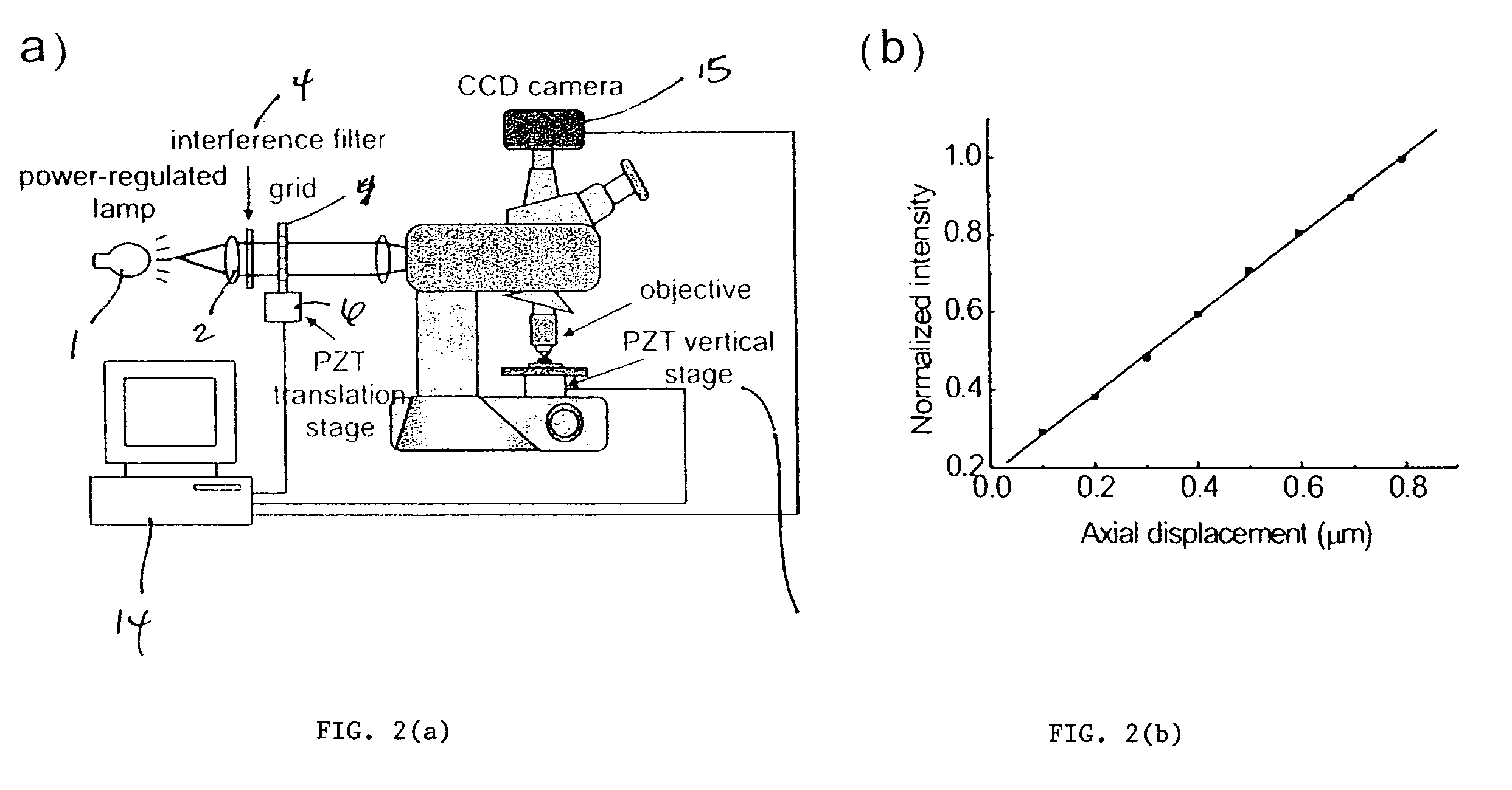
"The patent describes a system and method for measuring the refractive indices and thicknesses of transparent thin-films using a microscope. The system combines three principles: wide field optical sectioning microscopy, differential confocal microscopy, and Fabry-Perot interferometry. The method uses a microscope objective to capture images of the thin-film, and the lateral resolution is determined based on the Rayleigh criterion. The system does not rely on polarization of light, making it easy to construct and calibrate. The technical effects of the invention include improved accuracy and efficiency in measuring refractive indices and thicknesses of transparent thin-films."

Problems solved by technology

Another recent proposed solution for achieving sub-micrometer lateral resolution involved the use of a high-resolution imaging ellipsometer using a high numerical aperture (NA) microscope objective as a probe.5 However, such a proposed solution does not indicate that the simultaneous measurement of n and d of inhomogeneous thin-films can be achieved.

Method used


Image

  • Method for characterizing transparent thin-films using differential optical sectioning interference microscopy
  • Method for characterizing transparent thin-films using differential optical sectioning interference microscopy
  • Method for characterizing transparent thin-films using differential optical sectioning interference microscopy

Examples


Embodiment Construction

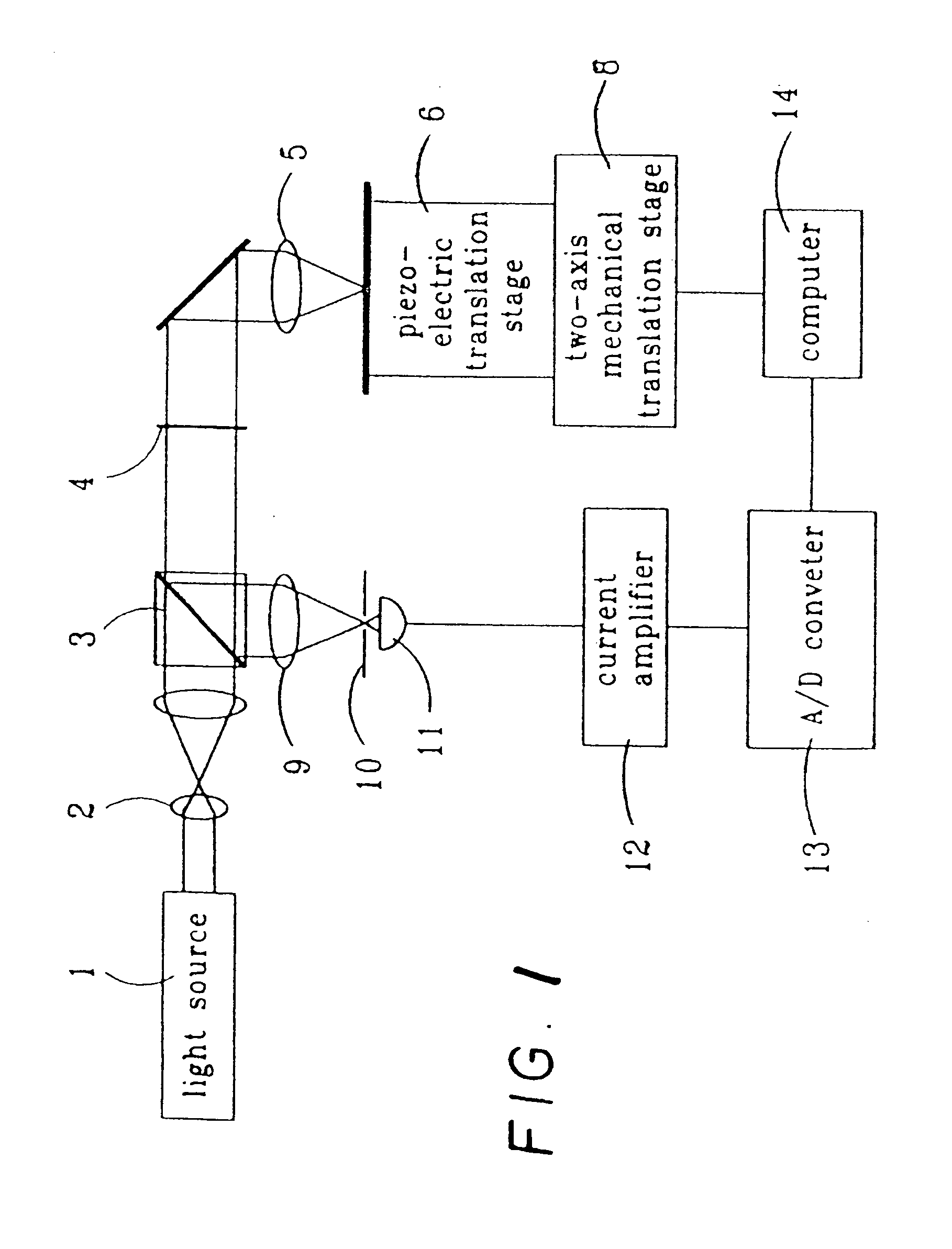
[0021]FIG. 1 is an illustration of an exemplary “differential confocal microscopy”. Such a system is described in detail in U.S. Pat. No. 5,804,813, the contents of which are incorporated herein in its entirety. With reference to FIG. 1, light source 1 emits a beam through a beam expander 2, and the beam is then focused by the focusing device 5 onto a sample which is at the top of a piezo-electric translator (PZT) 6. The sample is put on the PZT 6, and the PZT 6 is set up on computer-controlled two-axis mechanical translation stages 8. Before performing measurements, the distance between the sample is adjusted, and the focusing device 5 is adjusted to the focal length of the focusing device by maximizing the detected signal, and the PZT 6 is adjusted to move the sample to the linear slope region of the axial response curve of confocal microscopy, which is the working range of the present “differential confocal microscopy” of the present invention.

[0022]The two-axis mechanical transl...


PUM

PropertyMeasurementUnit
transparentaaaaaaaaaa
refractive indicesaaaaaaaaaa
thicknessesaaaaaaaaaa

Abstract

An imaging, differential optical sectioning interference microscopy (DOSIM) system and method for measuring refractive indices and thicknesses of transparent thin-films. The refractive index and thickness are calculated from two interferometric images of the sample transparent thin-film having a vertical offset that falls within the linear region of an axial response curve of optically sectioning microscopy. Here, the images are formed by a microscope objective in the normal direction, i.e., in the direction perpendicular to the latitudinal surface of the thin-film. As a result, the lateral resolution of the transparent thin-film is estimated based on the Rayleigh criterion, 0.61λ / NA.

Description

BACKGROUND OF THE INVENTION[0001]1. Field of the Invention[0002]The present invention relates to transparent thin-films and, more particularly, to an imaging, differential optical sectioning interference microscopy (DOSIM) system and method for measuring refractive indices n and thicknesses d of transparent thin-films.[0003]2. Description of the Related Art[0004]Refractive indices (n) and thicknesses (d) of thin-films are essential parameters for modern electronic and optoelectronic devices. At present, ellipsometers are the preferred tool for measuring refractive indices and thicknesses of transparent thin-films.1 Such conventional ellipsometers use an obliquely incident light path to illuminate the specimens films. However, the geometry associated with such conventional ellipsometers tends to increase the lateral resolution of the measurement in the order of larger than tens of micrometers.[0005]A variety of imaging ellipsometers have been developed to improve the lateral resoluti...

Claims


Application Information

Patent Timeline
Patent Type & Authority Applications(United States)
IPC IPC(8): G01N21/00G06F15/00
CPCG01B9/04G01B11/0633G01N21/45G01N21/8422G01N2021/4126
Inventor LEE, CHAU-HWANGWANG, CHUN-CHIEH
Owner ACAD SINIC
Learn More