Molecular separator

Active Publication Date: 2008-11-06
TERVITA +1
View PDF40 Cites 68 Cited by
  • Summary
  • Abstract
  • Description
  • Claims
  • Application Information

AI Technical Summary

Benefits of technology

[0014]The present invention discloses a method and apparatus for separating particles, dissolved matter and chemical sub-fractions from a fluid stream. In one embodiment, the present invention also discloses a novel separator design which creates or enhances particle kinetics and cavitation physics to increase filtration efficiency and provides for the separation of chemical sub-fractions from fluid streams below one micron in size. In one aspect, the untreated fluid is placed under pressure sufficient to enhance standard filtration, create or enhance particle kinetic reactions, and/or to create or enhance hydrodynamic cavitation during the separation process wherein suspended and dissolved contaminants are separated from the fluid stream within the separator by one or more of said processes during the separation phase. The treated fluid may then be transported to a product collection tank, disc

Problems solved by technology

The safe and effective removal of contaminants from fluids is a consistent problem faced by many industries.
The presence of suspended and/or dissolved solids in waste fluid and other fluids is undesirable for several reasons.
If established discharge-contamination levels are exceeded, governmental authorities and agencies may impose surcharges and penalties on the entity responsible for the discharge of fluids which do not meet or exceed the appropriate standard of quality.
For example, both terrestrial and offshore oil and gas fields produce large quantities of contaminated fluid that can have significant environmental effects if they are not handled, remediated and discharged properly.
As a result, increasing volumes of both formation fluid and injected fluid are produced and remain untreated in the recovery of oil and gas from the formation.
The treatment of untreated fluid is a major component of the cost of producing oil and gas.
Other contaminants may include slurries having dispersed oil droplets, dissolved organic compounds including dissolved oil, drilling fluids, polymers, well treatment and workover chemicals, and other organic and inorganic compounds that can lead to toxicity.
Because of the contaminants in untreated fluid, it requires no large amount of thought to surmise that the direct release or reinjection of untreated fluid into the ocean, upon land, or into the subsurface formation would have damaging effects on the environment and pose health risks to animals and humans in both the short and long term.
There

Method used


Image

  • Molecular separator
  • Molecular separator
  • Molecular separator

Examples


Embodiment Construction

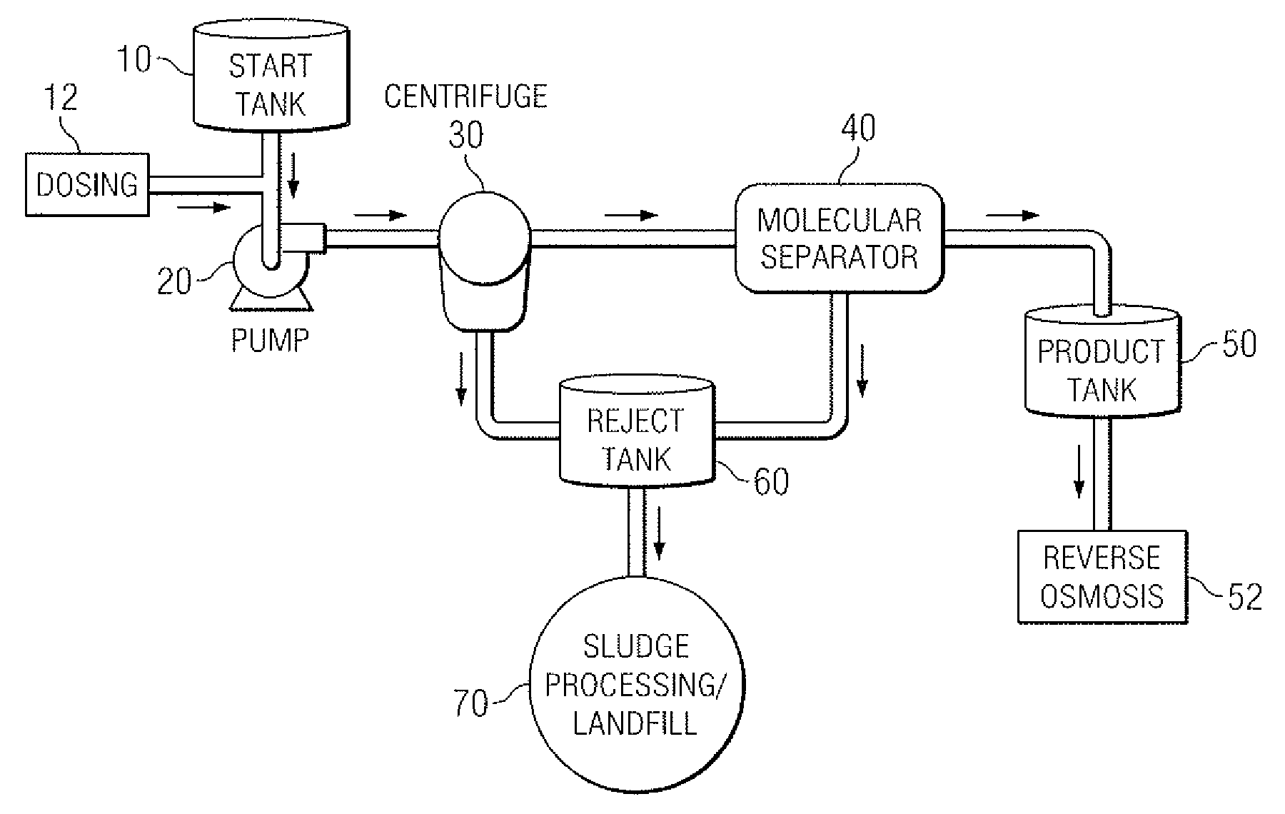
[0029]The present invention is directed towards an improved fluid treatment system for removing contaminants from a variety of fluids, including but not limited to, waters, synthetic fluids, oil and petroleum based fluids, gases and other fluids occurring naturally and which are also manmade. In one embodiment, the use of hydrodynamic cavitation forces and physics in conjunction with traditional separation media to treat contaminated fluid is both novel and a significant improvement over existing filtration systems. “Untreated fluid” or “influent fluid” is used throughout the detailed description and refers to any fluid containing one or more contaminants. As used herein “untreated fluid” is used interchangeably with “influent fluid.” As used herein, “contaminant” refers to any physical, chemical, biological, or radiological substance or matter which is to be entirely or substantially removed from the fluid in which the contaminant is suspended, dissolved or otherwise entrained.

[003...


PUM

PropertyMeasurementUnit
Flow rateaaaaaaaaaa
Magnetic fieldaaaaaaaaaa
Efficiencyaaaaaaaaaa

Abstract

The present invention discloses a method and apparatus for separating particles and dissolved matter from an untreated fluid stream. Specifically, the present invention includes a first pressure source which transports untreated fluid or contaminated aqueous fluid into a separator annulus with a filter element disposed therein. The untreated fluid is placed under appropriate pressure sufficient to produce turbulent flow, increased particle kinetics and/or cavitation allowing the desired fluid to penetrate and pass into and through the filter media. The treated fluid is then transported to a collection tank. The contaminant matter retained by the filter media may be removed by the nearly instantaneous reverse pressurization of the separator annulus by a second pressure source thereby removing the contaminant particles away from contact with the filter media, and which may then be transported to a waste collection tank or a separator for further treatment.

Description

CROSS-REFERENCES TO RELATED APPLICATIONS[0001]This application is a continuation-in-part and claims the benefit of and priority to co-pending U.S. patent application Ser. No. 11 / 042,235, attorney docket no. CJOHN.00002CIP which was filed on Jan. 25, 2005, which claims the benefit of and priority to U.S. Pat. No. 7,291,267, attorney docket no. CJOHN.00002 filed on Apr. 8, 2004, which claims the benefit of and priority to U.S. Provisional Application No. 60 / 540,492, filed Jan. 30, 2004, the disclosures of which are incorporated herein by reference.STATEMENT REGARDING FEDERALLY SPONSORED RESEARCH OR DEVELOPMENT[0002]Not applicable.NAMES OF PARTIES TO A JOINT RESEARCH AGREEMENT[0003]Not applicable.INCORPORATION BY REFERENCE OF MATERIAL SUBMITTED ON A COMPACT DISC[0004]Not applicable.BACKGROUND OF THE INVENTION[0005]1. Technical Field[0006]The present invention relates to an improved apparatus and system for improving the quality of fluids untreated from petroleum and gas well drilling a...

Claims


Application Information

Patent Timeline
IPC IPC(8): B01D29/68B01D37/00B01D61/00
CPCB01D17/0202B01D61/00B01D61/025B01D61/027B01D61/14B01D61/142B01D61/18B01D61/20B01D61/58B01D63/06B01D65/00B01D65/02B01D65/08B01D2313/44B01D2317/025B01D2321/00B01D2321/2075C02F1/32C02F1/36C02F1/38C02F1/441C02F1/444C02F1/48C02F9/00C02F2103/32F04B9/113B01D17/085B01D61/146
Inventor JOHNSON, RAYMOND FORD
Owner TERVITA
Why Eureka
Try Eureka