Internal Combustion Engine

a combustion engine and internal combustion technology, applied in the direction of electrical control, process and machine control, instruments, etc., can solve the problems of loud combustion noise, increased pressure (cylinder pressure), and knocking, so as to improve fuel economy and nox emissions from the internal combustion engine. , the effect of stably carried ou

Active Publication Date: 2008-11-06
TOYOTA JIDOSHA KK
View PDF10 Cites 32 Cited by
  • Summary
  • Abstract
  • Description
  • Claims
  • Application Information

AI Technical Summary

Benefits of technology

[0100]In such a uniflow-type 2-cycle internal combustion engine, high-temperature combustion gas can be immediately utilized for raising the temperature of an air/fuel mixture to be subjected to next combustion, so that auto-ignition combustion can be stably carried out. Thus, an operation region in which the auto-ignition operation can be performed can be expanded to cover a region of lighter load. As a result, NOx emissions from the internal combustion engine can be reduced more, and fuel economy can further be improved.
[0101]Here, in an ordinary internal combustion engine having an intake valve and an exhaust valve that are provided on a cylinder head, as load inc...

Problems solved by technology

Since auto-ignition combustion completes within a very short period of time, auto-ignition combustion in a high-load region, which requires a large amount of fuel, causes an abrupt increase in pressure (cylinder pressure) within the combustion chamber, and therefore, very loud combustion noise may be caused.
Accordingly, if the internal combustion engine which can perform auto-ignition combustion performs spark ignition combustion when the load is high, knocking arise...

Method used


Image

  • Internal Combustion Engine
  • Internal Combustion Engine
  • Internal Combustion Engine

Examples


first embodiment

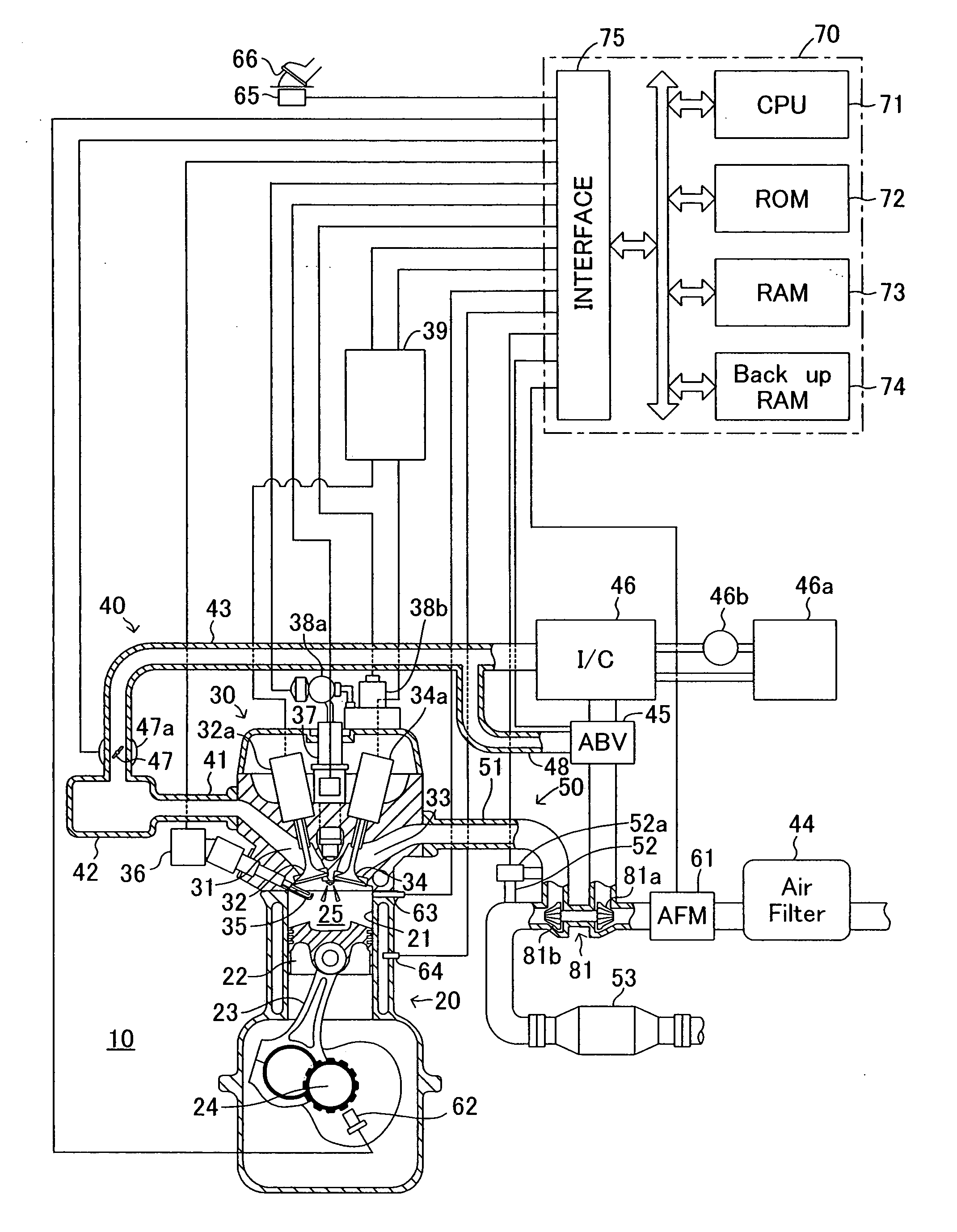
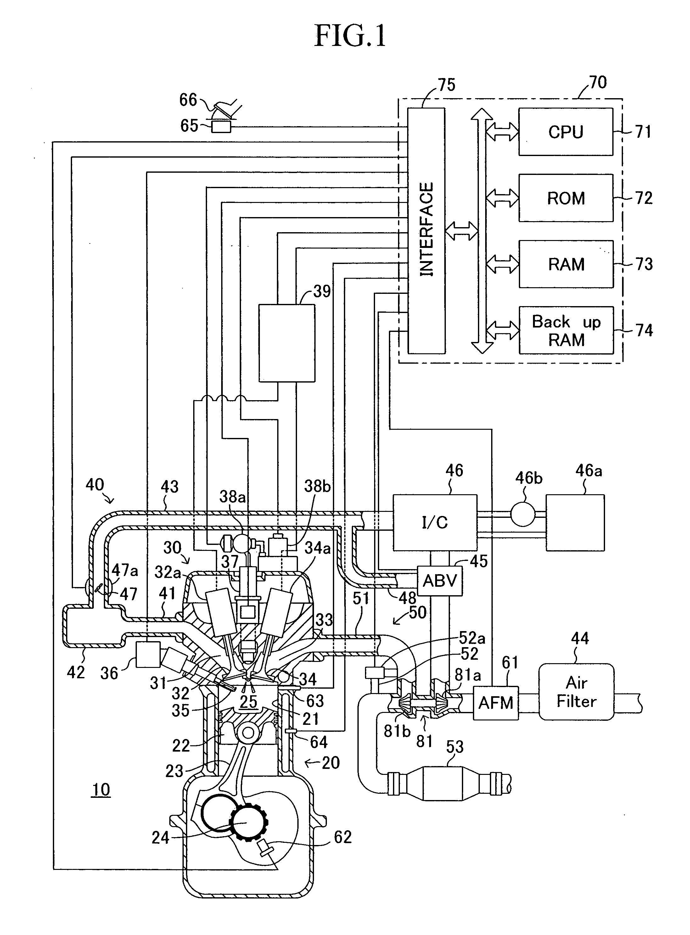
[0124]Embodiments of an internal combustion engine according to the present invention will next be described with reference to the drawings. FIG. 1 shows a schematic configuration of an internal combustion engine 10 according to a first embodiment of the present invention. FIG. 1 shows a section of a specific cylinder only, but other cylinders also have a similar configuration.

[0125]The internal combustion engine 10 is a piston-reciprocating-type 4-cycle internal combustion engine configured so as to perform a 4-cycle operation in which, every 720 degrees of crank angle, an intake stroke, a compression stroke, a combustion stroke, and an exhaust stroke are repeated. The internal combustion engine 10 uses gasoline as fuel.

[0126]The internal combustion engine 10 includes a cylinder block section 20 including a cylinder block, a cylinder block lower case, and an oil pan; a cylinder head section30 fixed on the cylinder block section 20; an intake system 40 for supplying air to the cylin...

second embodiment

[0235]Next, an internal combustion engine according to a second embodiment of the present invention will be described. This internal combustion engine differs from the internal combustion engine 10 according to the first embodiment only in that the following functions are added to the operation changeover means G1. The following description will be focused on the difference.

[0236](Changeover from the Homogeneous-Premixed-Charge Compression Auto-Ignition Operation to the Stratified-Charge Auto-Ignition Combustion Operation)

[0237]As mentioned above, the operation changeover means G1 makes selection from among the operation execution means F1 to F4 in accordance with the operation region map shown in FIG. 7, thereby changing over operation.

[0238]Furthermore, in the case where the premixed-charge compression auto-ignition combustion operation execution means F2 is executing a premixed-charge compression auto-ignition combustion operation which combusts a homogeneous air / fuel mixture, th...

third embodiment

[0248]Next, an internal combustion engine according to a third embodiment of the present invention will be described. This internal combustion engine has a configuration similar to that of the internal combustion engine 10. However, this internal combustion engine is a 2-cycle internal combustion engine configured so as to perform a 2-cycle operation in which, every 360 degrees of crank angle, an exhaust stroke is started through establishment of communication between the combustion chamber 25 and the exhaust ports 33 (through opening of the exhaust valves 34) while communication is cut off by closing intake valves 32 between the combustion chamber 25 and the intake ports 31 which are configured so as to generate an intake air swirl within the combustion chamber 25; next, a scavenging stroke is started through establishment of communication between the combustion chamber 25 and the intake ports 31 (through opening of the intake valves 32); next, an intake stroke is started through c...


PUM


Abstract

An internal combustion engine 10 includes a fuel injection valve 37 for injecting a gasoline fuel into a combustion chamber 25, and a spark plug 35. When the internal combustion engine is operated in a light-load region, the fuel is injected at an early and/or middle stage of an intake strode, whereby a homogeneous air/fuel mixture is formed and compressed to thereby perform a premixed-charge compression auto-ignition operation in which the fuel is auto-ignited and combusted. When the internal combustion engine is operated in a middle-load region, a spark-ignition combustion operation is performed. When the internal combustion engine is operated in a high-load region, air taken into the combustion chamber is compressed, and the fuel is injected into the compressed air, thereby performing a diffusion combustion operation in which the fuel is diffusion-combusted.

Description

TECHNICAL FIELD[0001]The present invention relates to an internal combustion engine in which a mixture of air and gasoline fuel formed in a combustion chamber can be auto-ignited through compression.BACKGROUND ART[0002]It is known that the amount of NOx produced from an internal combustion engine which combusts (burns) gasoline as a fuel depends on a combustion period of time during which the temperature in a combustion chamber is high temperature, and becomes smaller as the combustion period of time shortens. In premixed-charge compression auto-ignition (self-ignition) combustion in which an air / fuel mixture formed in the combustion chamber is compressed at high compression ratio to thereby be ignited, the compressed air / fuel mixture is ignited substantially simultaneously at a large number of scattered positions. Accordingly, auto-ignition combustion completes within a shorter period of time than spark ignition combustion in which fuel is combusted through propagation of flame. Th...

Claims


Application Information

Patent Timeline
IPC IPC(8): F02D45/00
CPCF02B1/12F02D2041/3052F02B17/005F02B23/101F02B23/104F02B25/04F02B29/0418F02B29/0437F02B37/18F02B2023/102F02B2023/103F02B2023/108F02B2031/006F02B2075/125F02D13/0215F02D13/0269F02D35/023F02D35/027F02D41/064F02D41/3029F02D41/3035F02D41/3041F02D41/3058F02D2041/001F02D2041/0015F02D2400/02F02D2400/04F02M61/042F02M61/1813F02M61/182Y02T10/12Y02T10/125Y02T10/128Y02T10/123Y02T10/142F02B11/00
Inventor KOBAYASHI, TATSUO
Owner TOYOTA JIDOSHA KK
Why Eureka
Try Eureka