Control apparatus for electric vehicles

a technology for controlling apparatus and electric vehicles, applied in the direction of electric energy management, electric devices, special data processing applications, etc., can solve the problems of excessive voltage appearing on damage to electronic equipment connected to the power supply line, and inability to absorb the voltage of the line, etc., to reduce torque variation, small size, and low cost

Active Publication Date: 2008-11-13
DENSO CORP
View PDF22 Cites 26 Cited by
  • Summary
  • Abstract
  • Description
  • Claims
  • Application Information

AI Technical Summary

Benefits of technology

[0008]It is thus an object of the present invention to improve a control apparatus for an electric vehicle to be capable of stabilizing a voltage appearing on a power supply line in small size and low cost and to be capable of reducing a torque variation to nearly zero in a transient condition of controlling an input power to a motor unit.
[0009]According to one aspect, in a control apparatus for an electric vehicle, a voltage supplied by a DC power source into a system voltage appearing on a power supply line is converted and an MG unit includes an inverter connected to the power supply line and drives an AC motor. A torque of the AC motor and an input electric power of the MG unit are controlled by supplying the AC motor with a pulse waveform voltage, which commutates the AC motor at every predetermined electric angle, based on a torque command value of the AC motor and an input electric power command value of the MG unit. The system voltage is stabilized by outputting the input electric power command value to the torque and power control means, so that a system voltage variation which is a variation from a target value of the system voltage is suppressed by input electric power control of the MG unit.
[0010]Specifically, in controlling the torque and the input electric power of the MG unit, a torque control detection current related to torque control of the AC motor is separated from a detection motor current flowing in the AC motor. A first estimated torq

Problems solved by technology

When a relation between electric power driving one of the AC motors and electric power generated by the other AC motor considerably varies due to changes in vehicle operating state or another reason, however, a voltage variation caused by a change in such relation as a voltage variation of the power supply line cannot be absorbed by the voltage boosting converter and/or the smoothing capacitor.
Thus, the voltage appearing on the power supply line becomes excessively high.
As a result, it is likely that electronic equipment connected to the power supply line is damaged.
By adoption of this method, however, the voltage boosting converter with better performance and the smoothing capacitor with a larger capacitance will inevitably raise the cos

Method used


Image

  • Control apparatus for electric vehicles
  • Control apparatus for electric vehicles
  • Control apparatus for electric vehicles

Examples


Embodiment Construction

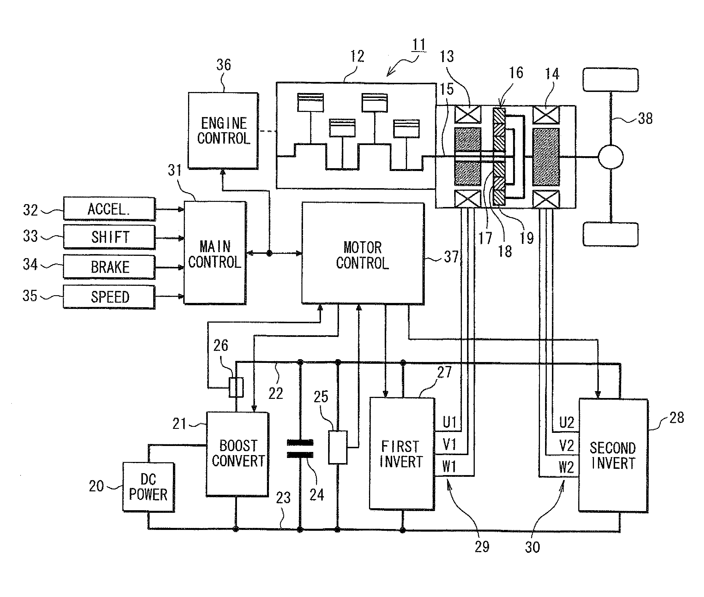
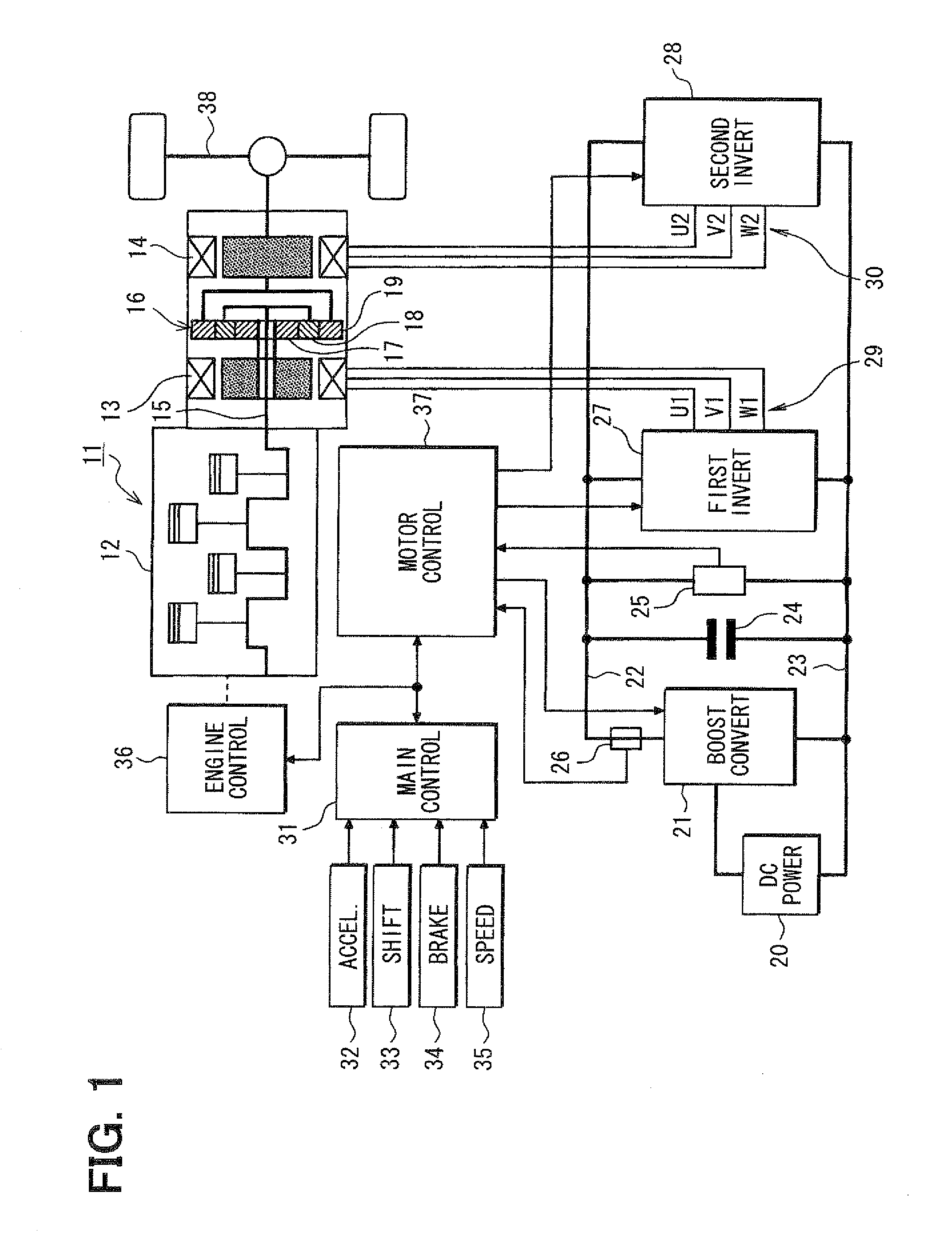
[0017]Referring first to FIG. 1, an electric vehicle 11 has an internal combustion engine 12 in addition to a first AC motor 13 and a second AC motor 14. Thus, the electric vehicle 11 is an engine / motor hybrid vehicle. The engine 12 and the second AC motor 14 are employed as drive power sources for driving the electric vehicle 11. Power generated by a crankshaft 15 of the engine 12 is divided into two paths by a planetary gear set 16. The planetary gear set 16 includes a sun gear 17, a planetary gear 18 and a ring gear 19. The sun gear 17 rotates at its radial center. The planetary gear 18 rotates along a circumference external to the sun gear 17 while revolving around its radial center The ring gear 19 rotates along a circumference external to the planetary gear 18. The planetary gear 18 is linked to the crankshaft 15 of the engine 12 through a carrier not shown in the figure. On the other hand, the ring gear 19 is linked to a rotation shaft of the second AC motor 14. The sun gear ...


PUM


Abstract

A motor control unit controls the input electric power of a MG unit to thereby suppress variations of a system voltage and stabilize the system voltage. The torque control of an AC motor and the input electric power control of the MG unit are executed independently from each other, so that the torque control and the input electric power control are stabilized. Further, torque variation zeroing control for correcting a phase of a pulse waveform voltage is executed so that a difference between a first estimated torque computed based on a torque control detection current vector of the AC motor and a second estimated torque computed based on a detection motor current vector is reduced to zero. Thus, uncomfortable torque variation is suppressed in a transient condition of the input electric power control of the MG unit.

Description

CROSS REFERENCE TO RELATED APPLICATION[0001]This application is based on and incorporates herein by reference Japanese Patent Application No. 2007-124336 filed on May 9, 2007.FIELD OF THE INVENTION[0002]The present invention relates to a control apparatus for an electric vehicle including a system for converting a voltage supplied by a DC power source into a system voltage by using a voltage converter and for driving an AC motor by applying the system voltage to the AC motor through an inverter.BACKGROUND OF THE INVENTION[0003]As disclosed in documents such as U.S. Pat. No. 7,099,756 (JP 2004-274945A), in an electric vehicle having AC motors mounted therein to serve as an energy source of the vehicle, the AC motors are each capable of serving as a motor for driving wheels of the vehicle as well as a motor driven by an engine to generate power. As the above system, a control apparatus for the electric vehicle includes a voltage boosting converter for raising a voltage supplied by a D...

Claims


Application Information

Patent Timeline
IPC IPC(8): B60W10/08B60L9/18B60L11/08B60W20/00B60L50/13B60L50/16H02P6/06H02P6/08H02P6/17H02P6/28H02P21/00H02P21/18H02P21/22H02P21/24H02P25/026H02P27/04H02P27/06H02P27/08
CPCB60K6/445Y02T10/6239B60L11/123B60L11/14B60L15/025B60L2210/14B60L2210/20B60L2220/14B60L2270/145B60W10/08B60W20/00H02P21/05Y02T10/6217Y02T10/643Y02T10/7077Y02T10/7225Y02T10/725Y10S903/906B60L11/08B60L50/13B60L50/16B60L50/61Y02T10/62Y02T10/64Y02T10/70Y02T10/7072Y02T10/72B60W20/10B60W2510/083B60W2510/086B60W2710/08
Inventor EGAMI, TSUNEYUKIKAWASAKI, SHINGO
Owner DENSO CORP
Why Eureka
Try Eureka