Magnetic Material Sensor and Detection Method Employing this Sensor, and Target Material Detection Sensor and Target Material Detection Kit

a technology of magnetic material and detection method, which is applied in the direction of magnetic beads labelled molecules, magnetic property measurements, instruments, etc., can solve the problems of inability to detect magnetic particles, and inability to invert the magnetization direction. achieve the effect of compact production

Inactive Publication Date: 2008-11-20
CANON KK
View PDF10 Cites 19 Cited by
  • Summary
  • Abstract
  • Description
  • Claims
  • Application Information

AI Technical Summary

Benefits of technology

[0010]To resolve these shortcomings, the objective of the present invention is to provide a magnetic material sensor that can be compactly produced and that can be employed, for a magnetoresistive effect film, to detect a magnetic material that enables the magnetization direction of a magnetic film to be changed by supplying a current to the magnetic material sensor, and whereby a change in the voltage of the magnetoresistive effect film, which occurs as a result of the interaction of a magnetic material to be detected and the magnetic film of the sensor, is employed to determine whether the magnetic material is present or absent, as well as the number of magnetic materials.

Problems solved by technology

For this method, high sensitivity is an advantage; however, there is a problem as regards the security of the radionuclide, and therefore, a special facility and a special apparatus are required.
However, when relative to the total area of the GMR film the ratio of the area influenced by a floating magnetic field, generated by a magnetic field, is considerably smaller, a remarkably weak detection signal is obtained, and the detection of magnetic particles is impossible.
However, when the size of the magnetic film is reduced, the inversion of the magnetization direction becomes more difficult, and the detection signal produced by a magnetic particle is weakened.
Furthermore, since means required to apply a uniform magnetic field to an area for the detection of a magnetic material must be large, the production of a compact sensor is not easy.

Method used


Image

  • Magnetic Material Sensor and Detection Method Employing this Sensor, and Target Material Detection Sensor and Target Material Detection Kit
  • Magnetic Material Sensor and Detection Method Employing this Sensor, and Target Material Detection Sensor and Target Material Detection Kit
  • Magnetic Material Sensor and Detection Method Employing this Sensor, and Target Material Detection Sensor and Target Material Detection Kit

Examples


first embodiment

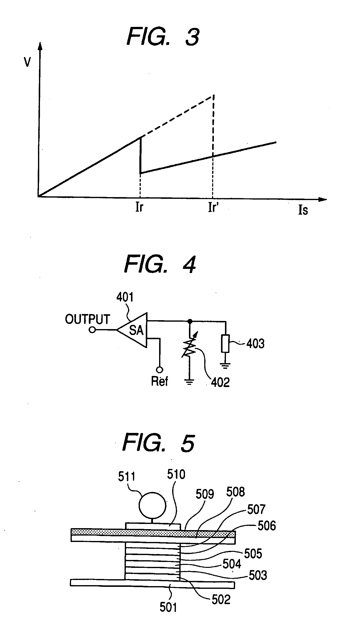
[0055]FIG. 5 is a conceptual diagram showing the structure of a magnetoresistive effect film used for the magnetic material sensor of the present invention, and the positional relationship of the film and a magnetic particle. A TMR film is employed as a magnetoresistive effect film, and a Al2O3 film is employed as a spin tunnel film 504. Further, an artificial antiferromagnetic film is deposited under the Al2O3 film and is used as a magnetized pinned layer. The magnetized pinned layer is provided by overlaying, on an lower electrode 501, a MnIr film 502 and a laminated film 503 consisting of a FeCo film, a Ru film and a FeCo film. Since the two FeCo films are magnetically coupled, and the magnetization directions are constantly antiparallel, magnetostatic coupling between the magnetized pinned layer and a detection layer or a magnetic material to be detected is weak. On the Al2O3 film, an exchange coupling film consisting of a FeCo film 505 and a NiFe film 506 is deposited and is us...

second embodiment

[0060]In the first embodiment, the rectangular TMR film that employs in-plane magnetized films has been used as a magnetic material sensor. However, the magnetic material sensor of this invention can be provided by employing perpendicular magnetized films.

[0061]In a second embodiment, an example for detecting small magnetic particles having a particle size of 50 nm will be explained. As in the first embodiment, a magnetic particle to be detected is coupled with the SH group, and a Au film is formed on the top of a magnetoresistive effect film. The circuit of a magnetic material sensor is the same as that in the first embodiment and the magnetoresistive effect film is a TMR film that, as shown in FIG. 7, is formed by laminating a TbFeCo alloy film, a FeCo alloy film, a Al2O3 film, a GdFeCo Alloy film and a Pt film in the named order. The TbFeCo alloy film is a perpendicular magnetized film having a composition that is superior in magnetization to the auxiliary lattice of a transition...

third embodiment

[0065]The magnetic material sensor of this invention can also be employed as a biosensor. In a third embodiment, an explanation will be given for a biosensor that detects a prostate specific antigen (PSA) that is known as a marker for prostate cancer.

[0066]A magnetoresistive effect film used for this embodiment has the same structure as the TMR film used for the first embodiment, and the particle size of a magnetic particle is about 100 nm.

[0067]In order to hold the primary antibody on the surface of an Au film that is deposited on the magnetoresistive effect film, the surface of the Au film is treated with a piranha solution (sulfuric acid:hydrogen peroxide=3:1), and is thereafter treated with a 1 mM ethanol solution of 10-carboxy-1-decanthiol. As a result, a self-organizing film (SAM) wherein a carboxyl group is represented is deposited on the surface. Furthermore, in order to immobilize the primary antibody, a soluble carbodiimide (WSC) and a N-hydroxysuccinimide react with each ...


PUM


Abstract

The present invention provides an appropriately produced magnetic material sensor having a small size.
The magnetic material sensor of this invention includes: a magnetoresistive effect film, formed using magnetic films; a current source, for supplying to the magnetoresistive effect film a current having a magnitude and a direction that can change the magnetization directions of the magnetic films; and a detector, for detecting the resistance of the magnetoresistive effect film.

Description

TECHNICAL FIELD[0001]The present invention relates to a magnetic material sensor and a detection method employing this sensor, and a target material detection sensor and a target material detection kit.BACKGROUND ART[0002]Many technologies, such as radio immunoassay (RIA or IRMA: immunoradiometric assay) and enzyme-antibody technique, have been proposed and employed for immunization analysis. According to radio immunoassay, a competitive antigen or an antibody is marked using a radionuclide, and a fixed quantity of the antigen is measured, based on the results of a specific activity. For this method, high sensitivity is an advantage; however, there is a problem as regards the security of the radionuclide, and therefore, a special facility and a special apparatus are required. Further, compared with radio immunoassay, enzyme-antibody technique, which employs an enzyme that is used to mark an antibody, is easier operationally, and satisfies requirements for practical sensitivity; howe...

Claims


Application Information

Patent Timeline
Patent Type & Authority Applications(United States)
IPC IPC(8): G01R33/09
CPCB82Y25/00G01N15/0656G01N35/0098G01R33/09Y10S436/806G01R33/12G01R33/1269G01R33/1284G01R33/093
Inventor IKEDA, TAKASHI
Owner CANON KK
Why Eureka
Try Eureka