
Method and Transmitter, Receiver and Transceiver Systems for Ultra Widebrand Communication

a technology of transmitter and receiver, applied in the field of cyclically extended cdma systems, can solve the problems of slow convergence time and complicated computation, inability to effectively suppress ifi and mai, and limit the system capacity and maximum data rate that can be supported for available bandwidth, so as to reduce the computational load and/or power consumption of the system, and achieve the effect of reducing system performance and/or power consumption

Inactive Publication Date: 2008-11-27
AGENCY FOR SCI TECH & RES
View PDF7 Cites 24 Cited by
  • Summary
  • Abstract
  • Description
  • Claims
  • Application Information

AI Technical Summary

Benefits of technology

The invention is a system and method for transmitting signals using a spreader, sequence extender, and pulse shaper. The system and method allow for efficient processing of signals by removing chips from the received signals and shaping them to a desired format. This reduces the computational load and power consumption of the system without compromising its performance. The method also includes steps for selecting input signals, removing sequence extensions, and forming a frequency equalized signal. The technical effects of the invention include improved signal processing and reduced power consumption.

Problems solved by technology

Due to multipath delay spread of the wireless channel in such systems, inter-finger interference (IFI) and multiple access interference (MAI) are inherent with Rake receivers.
On the other hand, TDE receivers, although theoretically capable of suppressing IFI and MAI, suffer from slow convergence time and complicated computations when applied in DS-CDMA systems, and they are not able to suppress IFI and MAI effectively in practice.
Thus, conventional single carrier DS-CDMA systems are associated with inter-finger interference (IFI) and multiple access interference (MAI), which limit the system capacity and the maximum data rate that can be supported for available bandwidth.
Uncoded OFDM transmission techniques applied in a multipath environment have a bit error rate (BER) comparable to that of a narrow band radio channel because the fading of each subcarrier is frequency non-selective.
However, even though this technology can support high data rate and multiple users, it suffers from two major implementation difficulties.
The first is a high peak-to-average power ratio (PAPR) problem inherent with MC-CDMA systems and hence a highly linear (and inefficient) amplifier must be used to avoid distortion and spectral spreading.
The second problem is a high sensitivity to frequency offset and RF phase noise.
These conditions limit the applicability of MC-CDMA in practical wireless environments.
Thus, the performance of systems such as that described in U.S. Ser. No. 10 / 090,370 will be adversely affected.

Method used


Image

  • Method and Transmitter, Receiver and Transceiver Systems for Ultra Widebrand Communication
  • Method and Transmitter, Receiver and Transceiver Systems for Ultra Widebrand Communication
  • Method and Transmitter, Receiver and Transceiver Systems for Ultra Widebrand Communication

Examples


first embodiment

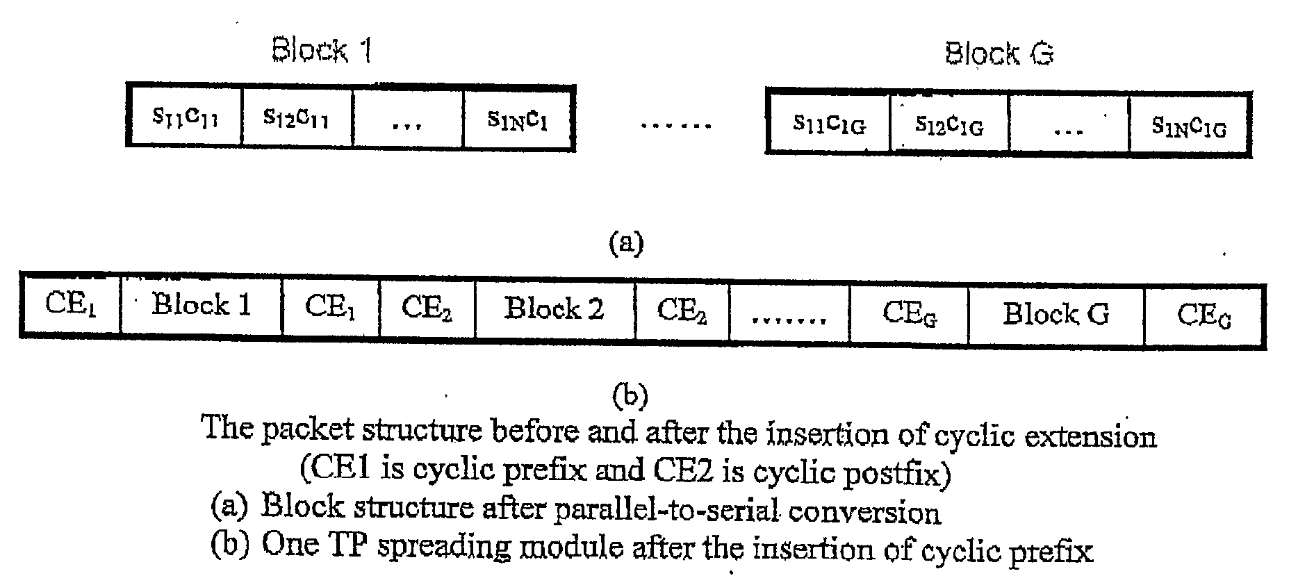
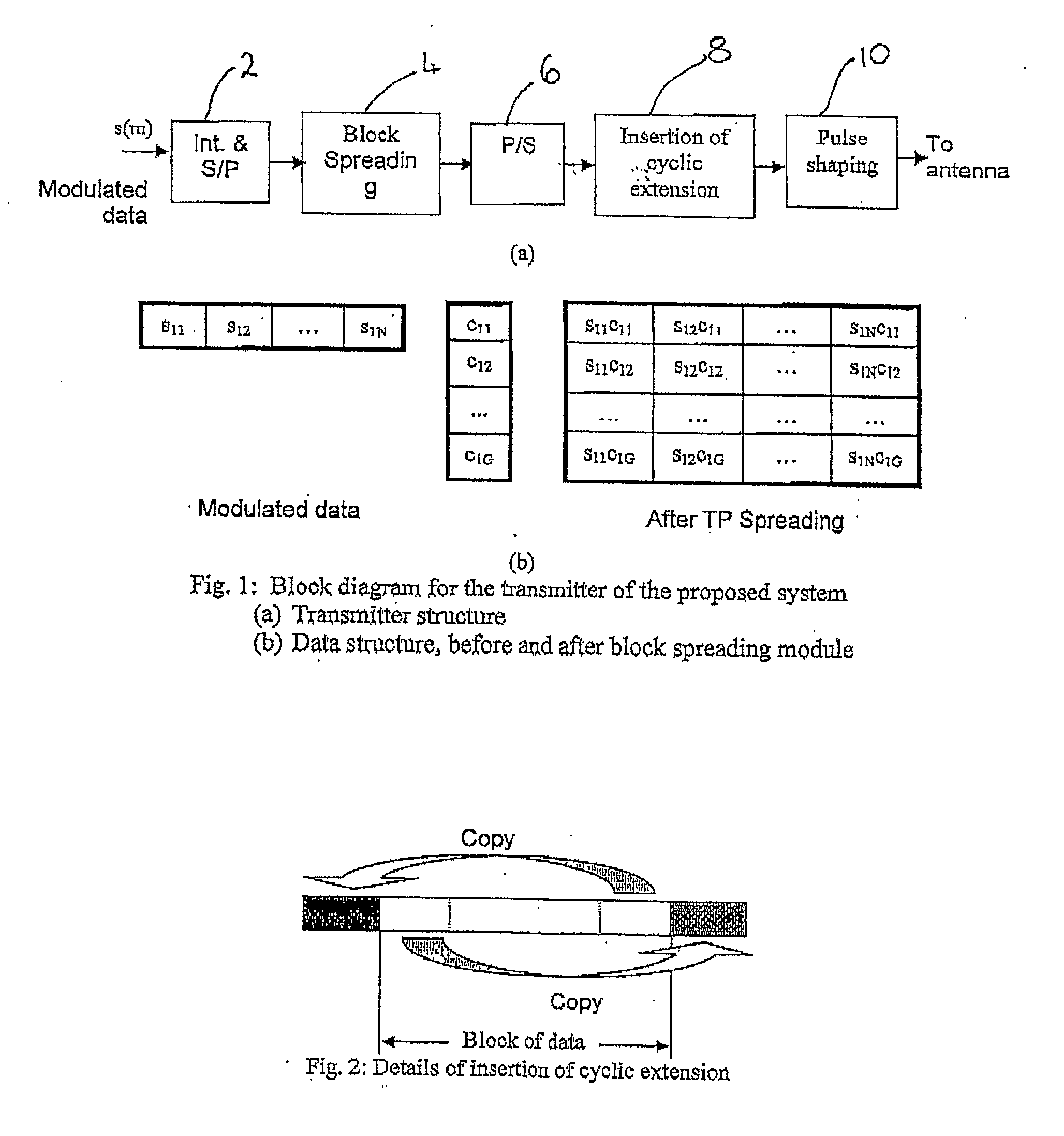
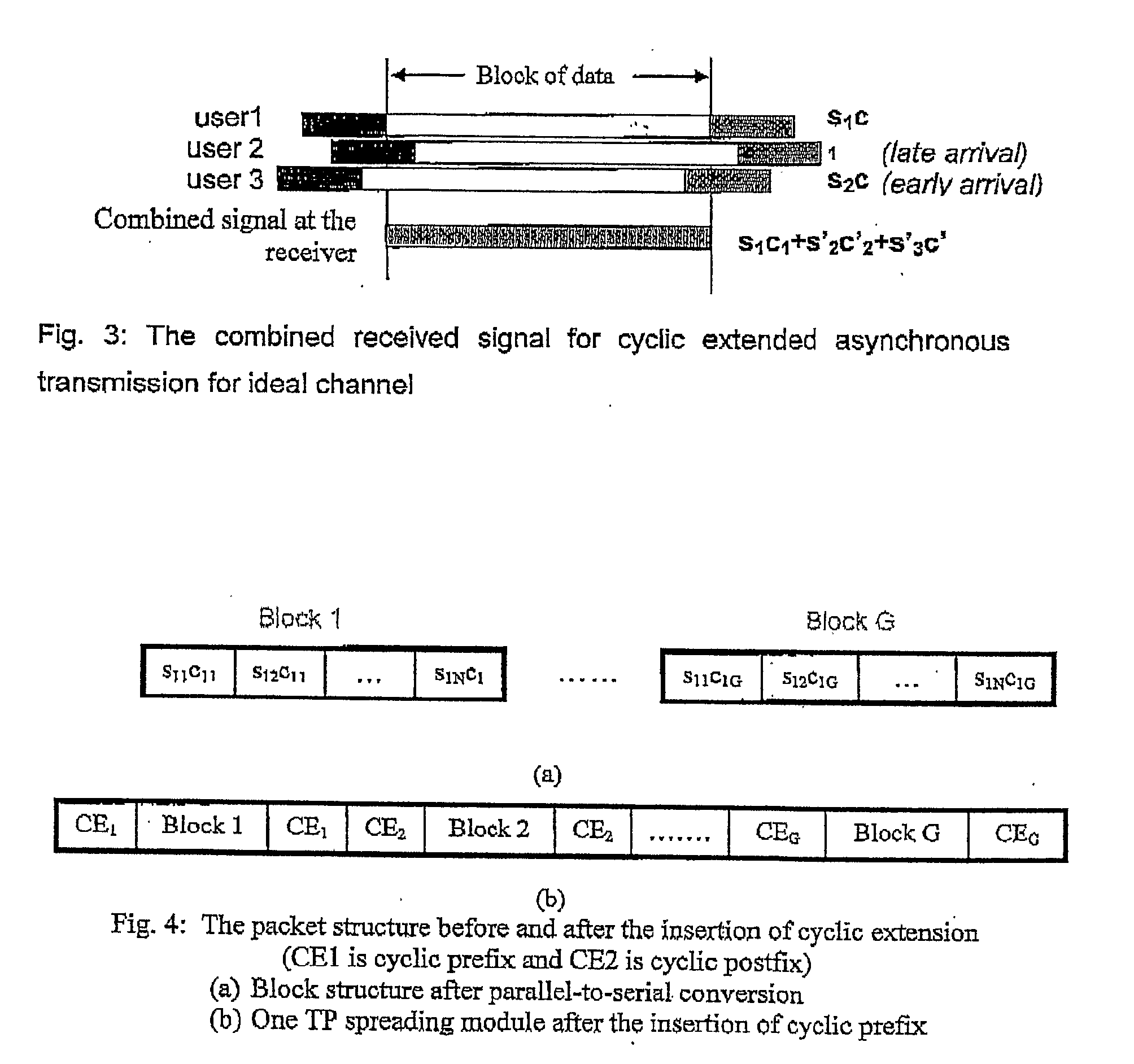
[0065]FIG. 1a shows the transmitter structure and FIG. 1b shows the packet structure of data being transmitted according to the present invention. As shown in these figures, the modulated data symbols s(m) from a first user are firstly converted from a serial sequence into a parallel sequence in a serial-to-parallel converter 2. An interleaver (indicated as Int. in the figure) is optionally added before the serial-to-parallel conversion to interleave signals from other users with the signal of the first user. The parallel sequence is then passed to a block spreader 4 and block spreading is applied to the sequence. The spread signal is then passed through a parallel-to-serial converter 6. A cyclic extension is then inserted into each block in the serial sequence in a cyclic extension insertion module 8. The cyclically extended signal is then subjected to pulse shaping in a pulse shaper block 10 and, after RF conversion, the signal is transmitted through a wireless channel.

[0066]As sh...

second embodiment

[0081]FIG. 7 shows a block diagram for a transmitter structure according to the present invention. The transmitter comprises a cyclic extension insertion module 30 for receiving the modulated data symbols s(m) from a first user. The output, in parallel form, is fed to a block spreading module 32, and the output signal of the block spreader module 32 is converted from a parallel sequence into a serial sequence in a parallel-to-serial converter 34. The serial sequence is then passed to a pulse-shaping filter 36 before transmission. In a preferred embodiment, an interleaver (not shown) may optionally be added before the cyclic insertion module to interleave signals from other users with the signal of the first user.

[0082]FIG. 7 also shows the packet structure of data being transmitted according to the second embodiment of the present invention. As described above in respect of FIG. 1b, the vector s1 (=s11, s12, . . . , s1N) denotes the modulated data symbols and c1 (=c11, c12, . . . , ...


PUM


Abstract

A system such as a code division multiple access (CDMA) system or an ultrawide band (UWB) system comprises a transmitter and a receiver. The transmitter includes a sequence extender for extending the incoming signal and a spreader for spreading the extended signal, the spreader input being coupled to the sequence extender output. A pulse shaper is coupled to the spreader output to provide a transmitter output signal. The transmitter output signal which has an associated chip rate is received by the receiver and is passed to a filter to select a number of input signals from the received signals. The signal is the passed to a sequence extension remover for removing a number of chips from the signal. The received signal is despread to a symbol rate which is less than the chip rate at which the received signal was spread prior to being received by the receiver. A frequency domain equalizer is provided to form a frequency equalized signal from the modified signal.

Description

FIELD OF THE INVENTION[0001]The present invention relates to a system, a transceiver structure for use therein and a method of processing signals in such a system. In particular, the invention relates to a cyclically extended CDMA system with frequency domain equalization,BACKGROUND OF THE INVENTION[0002]Direct sequence code division multiple access (DS-CDMA), is one of the effective wireless access technologies for supporting high system capacity, variable and high data rate transmission services and it has been adopted in the 3rd generation (3G) wireless communications systems.[0003]Conventional DS-CDMA systems are single carrier transmission systems. Typically, there are two kinds of receivers for use in a DS-CDMA system, namely a RAKE receiver and a time-domain equalization (TDE) receiver. The performance of the receiver depends on the properties of the wireless environment. Due to multipath delay spread of the wireless channel in such systems, inter-finger interference (IFI) an...

Claims


Application Information

Patent Timeline
Patent Type & Authority Applications(United States)
IPC IPC(8): H04B1/69H04B1/707H04L25/03
CPCH04B1/7103H04B1/71637H04L25/03159H04L2025/03375H04L2025/03522
Inventor CHIN PO SHIN, FRANCOISMADHUKUMAR, APPUKUTTAN NAIR SARASWATHY AMMA
Owner AGENCY FOR SCI TECH & RES
Learn More