
Catalyst carrier

a carrier and catalyst technology, applied in the field of catalyst carriers, can solve the problems of excessive excellent and deterioration of the carried catalyst, and achieve the effects of not easy to raise, excellent light-off characteristic, and easy to rais

Active Publication Date: 2008-11-27
NGK INSULATORS LTD
View PDF6 Cites 10 Cited by
  • Summary
  • Abstract
  • Description
  • Claims
  • Application Information

AI Technical Summary

Benefits of technology

[0005]The present invention has been developed in view of the above problem of a conventional technology, and an objective thereof is to provide a catalyst carrier in which a temperature is easily raised at a low temperature and which has an excellent light-off characteristic and in which the temperature is not easily raised at a high temperature and in which a maximum temperature can be minimized, whereby deterioration due to the heat of a carried catalyst can be suppressed.
[0019]According to the present invention there is disclosed a catalyst carrier in which a temperature is easily raised at a low temperature and which has an excellent light-off characteristic and in which the temperature is not easily raised at a high temperature and in which a maximum temperature can be minimized, whereby deterioration due to the heat of a carried catalyst can be suppressed.

Problems solved by technology

However, in a case where an exhaust gas is purified using a catalytic converter disclosed in Patent Document 1, to improve the light-off characteristic (a property capable of quickly achieving a catalyst activity temperature at a low temperature) of the catalytic converter, a catalyst carrier having a high OFA (opening ratio) has been used, but a temperature rise property is excessively excellent.
Therefore, on high load (high temperature, high flow rate) conditions, the catalyst carrier temperature becomes excessively high, which causes a problem that the carried catalyst deteriorates.

Method used


Image

  • Catalyst carrier
  • Catalyst carrier
  • Catalyst carrier

Examples


example 1

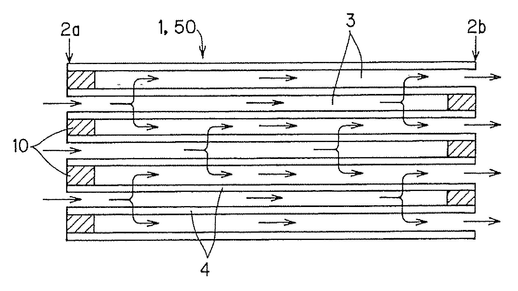
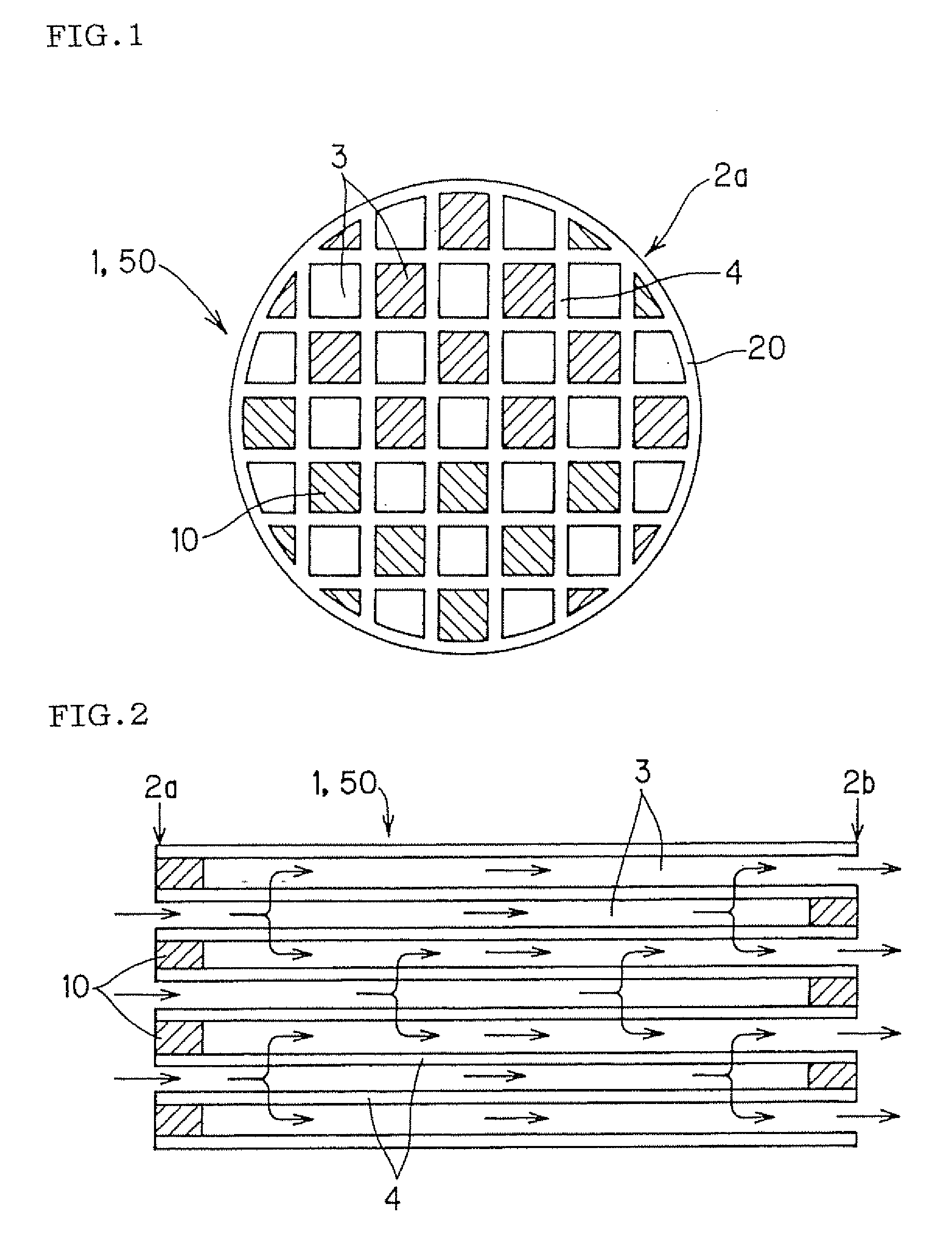
[0066]An alloy containing a main component of Zr, 1% to 1.5% of Sn, 0 to 0.2% of Fe, 0 to 0.2% of Cr, 0 to 1% of Ni and 0 to 0.02% of O2 was dispersed and held on the surfaces of cell partition walls of a cordierite honeycomb structure. An amount to be held was set so that a ratio of cordierite mass:alloy mass was 4:1. The alloy was dispersed and held as follows.

[0067]First, the cordierite honeycomb structure having a wall thickness of 2.5 mil (64 μm), a cell density of 400 cpsi (62 cells / cm2), a diameter of 105.7 mm and a length of 114.3 mm was prepared as a fired body by the existing manufacturing method.

[0068]As the alloy, a particle-like shape (an average particle diameter of 2 μm), and a configuration to be mixed in an alumina wash coat slurry were employed, and the cordierite honeycomb structure was coated with this slurry by a method similar to a usual alumina wash coat holding process. A thermal capacity changed owing to the phase transformation of this alloy, whereby the th...

example 2

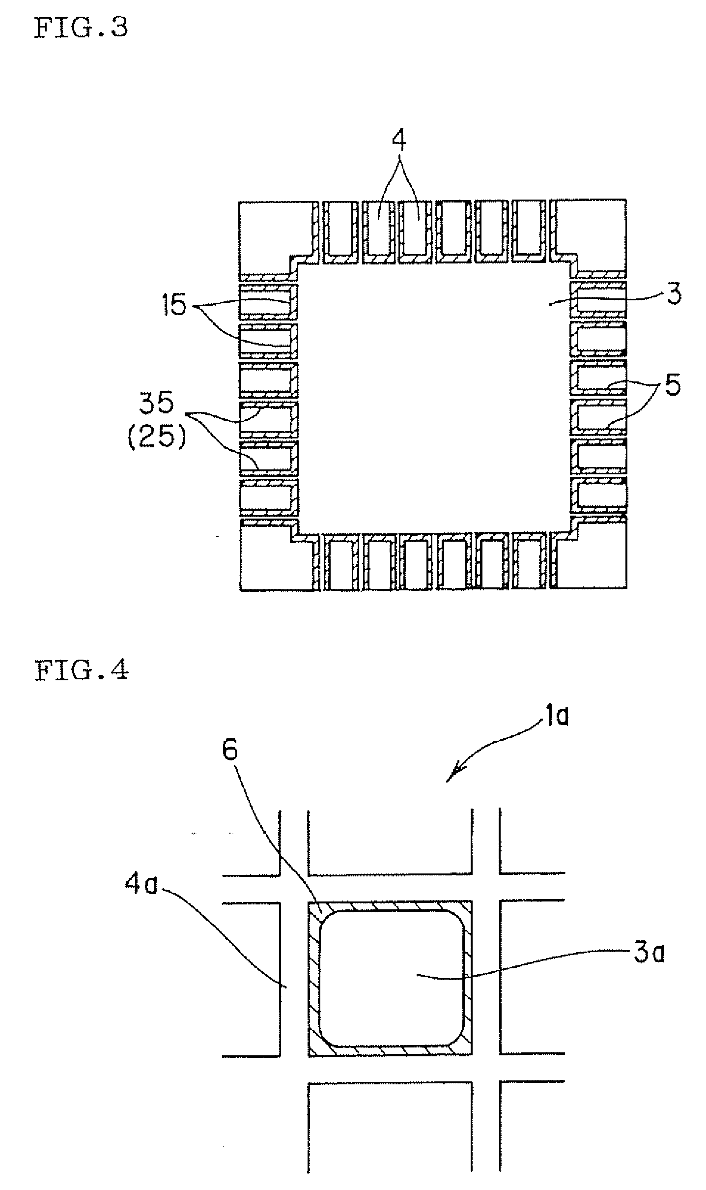
[0070]An alloy containing a main component of Zr, 1% to 1.5% of Sn, 0 to 0.2% of Fe, 0 to 0.2% of Cr, 0 to 1% of Ni and 0 to 0.02% Of O2 was dispersed and held in the pores of the cell partition walls of a cordierite honeycomb structure. An amount to be held was set so that a ratio of cordierite mass:alloy mass was 4:1. The alloy was dispersed and held as follows.

[0071]First the cordierite honeycomb structure having a wall thickness of 2.5 mil (64 μm), a cell density of 400 cpsi (62 cells / cm2), a diameter of 105.7 mm and a length of 114.3 mm was prepared as a fired body by the existing manufacturing method.

[0072]As the alloy, a particle-like shape (an average particle diameter of 2 μm), and a configuration to be mixed in an alumina wash coat slurry were employed, and the viscosity of this slurry was adjusted into such a low viscosity that the slurry easily entered the pores of the partition walls. The slurry including alloy particles was held in the pores of the partition walls in t...

example 3

[0079]A honeycomb structure was prepared using an alloy containing, as components, 17 to 20% of Cr, 5 to 6% of Al, 0.4 to 0.6% of Ti, 0.4 to 0.6% of Y2O3 and a remainder including Fe and a slight amount of impurities, and this structure was used as a catalyst carrier. This alloy was formed into a foil-like shape, and then provided with waveform unevenness, and this uneven foil and a flat foil were alternately superimposed and wound into a spiral form to prepare a honeycomb having a cylindrical outer periphery. The honeycomb structure having a wall thickness of 3.0 mil (75 μm), a cell density of 600 cpsi (93 cells / cm2), a diameter of 105.7 mm and a length of 114.3 mm was prepared. The thermal capacity of this alloy changed with temperature, and increased as much as about twice at a temperature exceeding 900° C. Therefore, a value of 800 J / kgK was obtained at 900° C., and this value was 2.0 times a value of 400 J / kgK at room temperature. A usual coat layer including a noble metal was ...


PUM

PropertyMeasurementUnit
Temperatureaaaaaaaaaa

Abstract

Disclosed is a catalyst carrier which is used for carrying a catalyst thereon. The catalyst carrier is characterized in that the apparent specific heat measured at 800° C. is 1.8 times or more greater than that measured at room temperature, wherein the apparent specific heat means a charge heat amount required for substantially increasing the temperature of a unit mass (kg) by 1 K, inclusive of the influence of endotherm or exotherm caused by change in crystalline form, partial melting, coagulation, phase transformation, vitrification, amorphous-formation, crystallization and the like.

Description

TECHNICAL FIELD[0001]The present invention relates to a catalyst carrier. More particularly, it relates to a catalyst carrier in which a temperature is easily raised at a low temperature and which has an excellent light-off characteristic and in which the temperature is not easily raised at a high temperature and in which a maximum temperature can be minimized, whereby deterioration due to the heat of a carried catalyst can be suppressed.BACKGROUND ART[0002]A catalytic converter which carries a catalyst for purification on a catalyst carrier is used in order to purify components to be purified, for example, carbon monoxide (CO), hydrocarbon (HC), nitrogen oxide (NOx), sulfur oxide (SOx) and the like included in an exhaust gas discharged from stationary engines for a car, a construction machine and an industry, a combustion device and the like. As such a catalytic converter, there is used a catalytic converter having a structure in which as shown in, for example, FIG. 8, a catalyst l...

Claims


Application Information

Patent Timeline
IPC IPC(8): B01D53/94B32B3/12
CPCB01D53/944B01J23/626B01J23/8993B01J35/002B01J35/04Y10T428/24149B01J37/0234B01J37/0244F01N3/2828F01N2330/06F01N2510/06B01J37/0217B01J35/30B01J35/56
Inventor MIYAIRI, YUKIO
Owner NGK INSULATORS LTD
Learn More