

Gas Diffusion Electrode and Solid Polymer Electrolyte Fuel Cell
a solid polymer electrolyte and gas diffusion electrode technology, applied in the direction of fuel cell details, electrochemical generators, cell components, etc., can solve the problems of insufficient water repellency, poor drainability of generated water, and insufficient water drainage under low humidification conditions, so as to reduce the humidification amount of oxidant gas, save fuel consumption, and suppress the effect of humidification power consumption
- Summary
- Abstract
- Description
- Claims
- Application Information
AI Technical Summary
Benefits of technology
Problems solved by technology
Method used
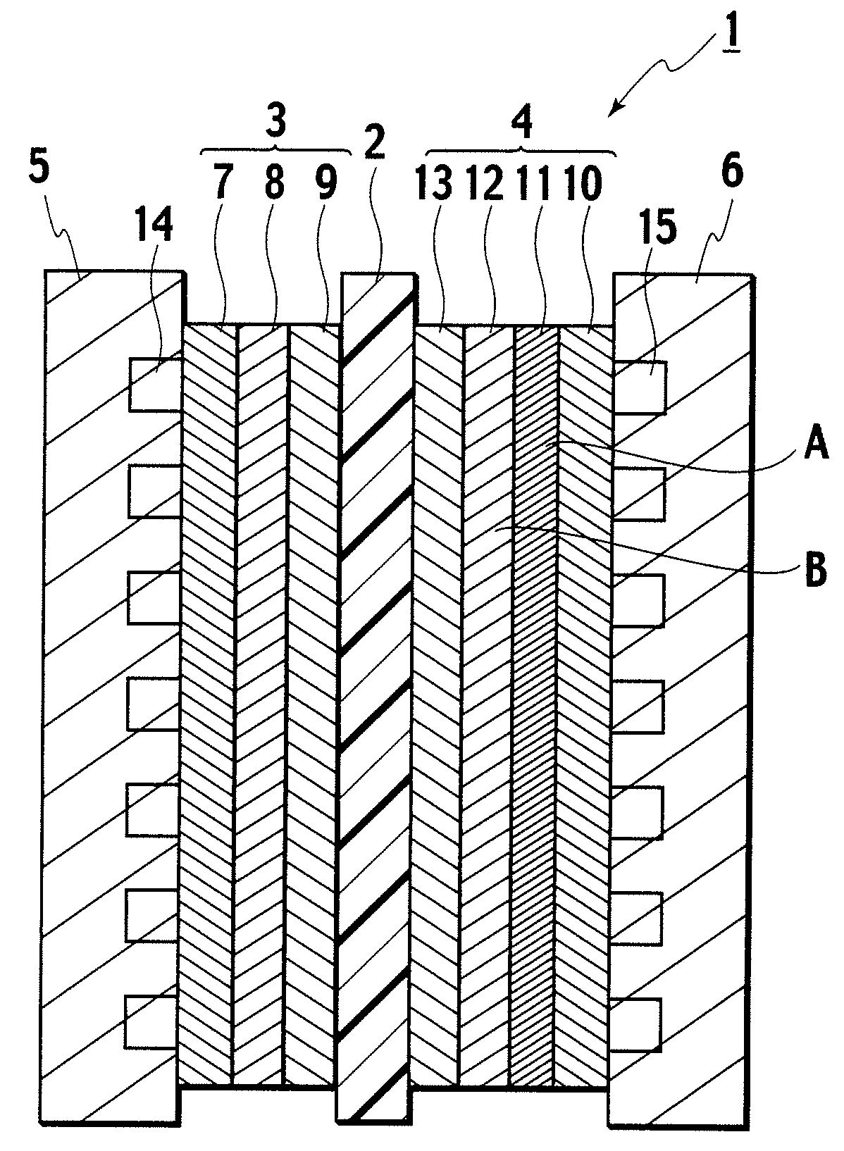
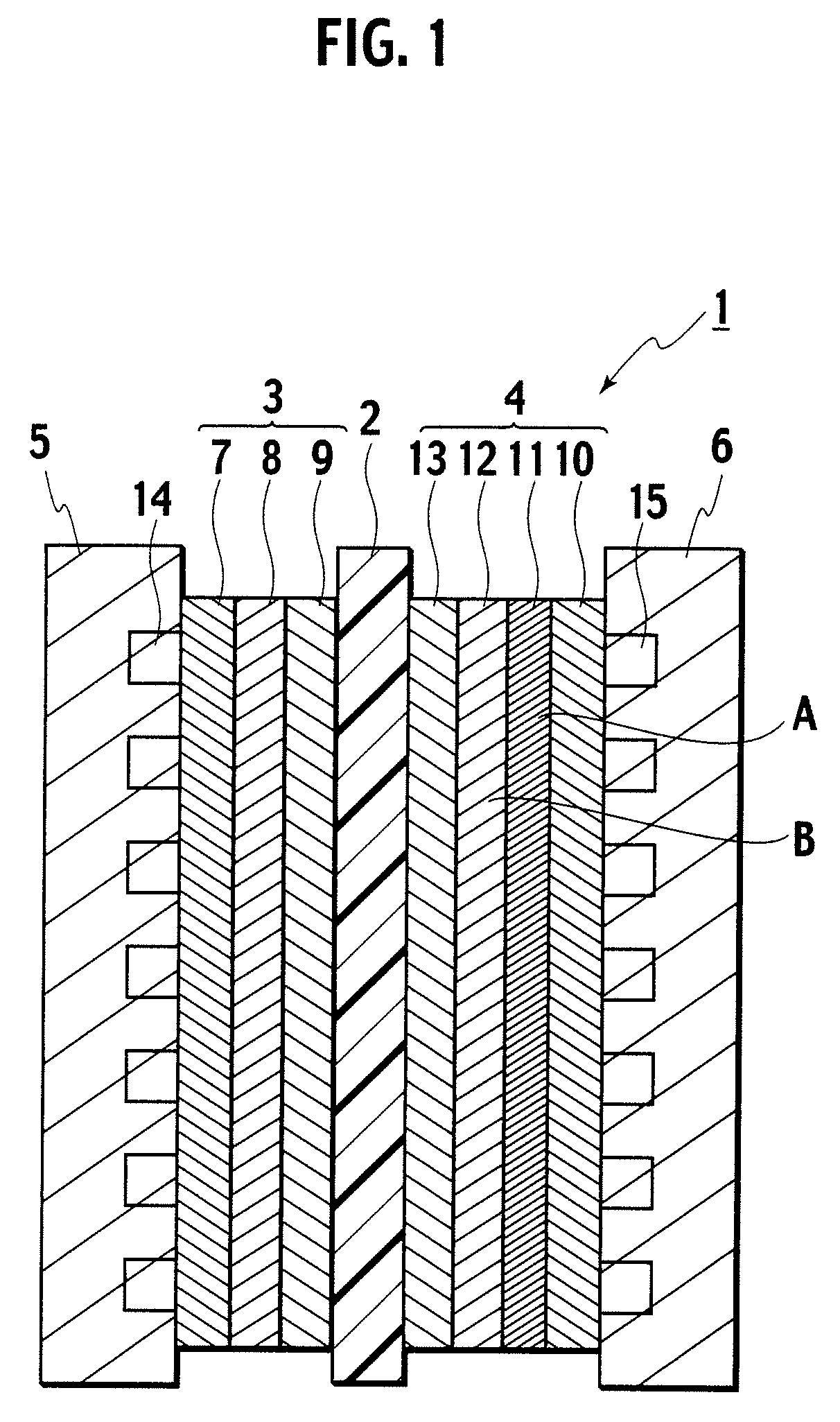
Image

Examples
example 1
Fabrication of CCM
[0051]Catalyst layers were formed on both surfaces of a polymer electrolyte membrane (Nafion 111 membrane, made by United States DuPont Corporation). As a catalyst which forms the catalyst layers, a Pt-carrying carbon catalyst (TEC10E50E) with a carrying amount of 50% was used.
[0052]A 5% Nafion solution (prepared by Aldrich Corporation), ultra pure water, IPA, and the Pt-carrying carbon catalyst were mixed together by every predetermined amount, were then agitated and mixed by using a rotary homogenizer, and catalyst ink was thus prepared. Note that the catalyst ink was prepared by the mixing while weighing ionomer and carbon so that weight ratios thereof could be 1.1:1.0.
[0053]Next, by using a screen printing method, the prepared catalyst ink was printed on one surface of each of two pieces of sheet-like PTFE so that the Pt-carrying amount could be 0.4 mg / cm2. Then, the catalyst ink thus printed was transferred to the polymer electrolyte membrane (Nafion 111 membr...
example 2
[0060]In Example 2, the fabrication method of the microporous layers was changed. Specifically, first, slurry was prepared, in which the PTFE-based fluid dispersion (prepared by Daikin Industries, Ltd.) and the carbon black particles (acetylene black: Denka Black OAB100, made by Denki Kagaku Kogyo Kabushiki Kaisha) were dispersively mixed together so that the ratio of the PTFE could be 20%. Next, slurry was prepared, in which the PTFE-based fluid dispersion (Daikin Industries, Ltd.) and carbon black particles (Ketjenblack EC (specific surface area: 800 m2 / g): carbon black made by Ketjenblack International Corporation) were dispersively mixed together so that the ratio of the PTFE could be 20%.
[0061]Thereafter, on the filter paper of which surface is smooth, the solution of Denka Black OAB100 and 20% PTFE was applied, and then water was suction-extracted therefrom. Thereafter, on the filter paper, a solution of Ketjenblack EC and 20% PTFE was applied, and water was suction-extracted ...
example 3
[0063]In Example 3, the fabrication method of the microporous layers was changed. Specifically, first, slurry was prepared, in which the PTFE-based fluid dispersion (prepared by Daikin Industries, Ltd.) and the carbon black particles (Vulcan XC-72R, made by Cabot Corporation) were dispersively mixed together in the wet process so that the ratio of the PTFE could be 20%. Next, slurry was prepared, in which the PTFE-based fluid dispersion (prepared by Daikin Industries, Ltd.) and the carbon black particles (Vulcan XC-72R, made by Cabot Corporation) were dispersively mixed together in the wet process so that the ratio of the PTFE could be 40%.
[0064]Thereafter, on the filter paper of which surface is smooth, a solution in which the ratio of the PTFE was 40% was applied, and then water was suction-extracted therefrom. Thereafter, on the filter paper, a solution in which the ratio of the PTFE was 20% was applied, and water was suction-extracted therefrom one more time. Subsequently, by th...
PUM
| Property | Measurement | Unit |
|---|---|---|
| Percent by mass | aaaaa | aaaaa |
| Percent by mass | aaaaa | aaaaa |
| Percent by mass | aaaaa | aaaaa |
Abstract
Description
Claims
Application Information