

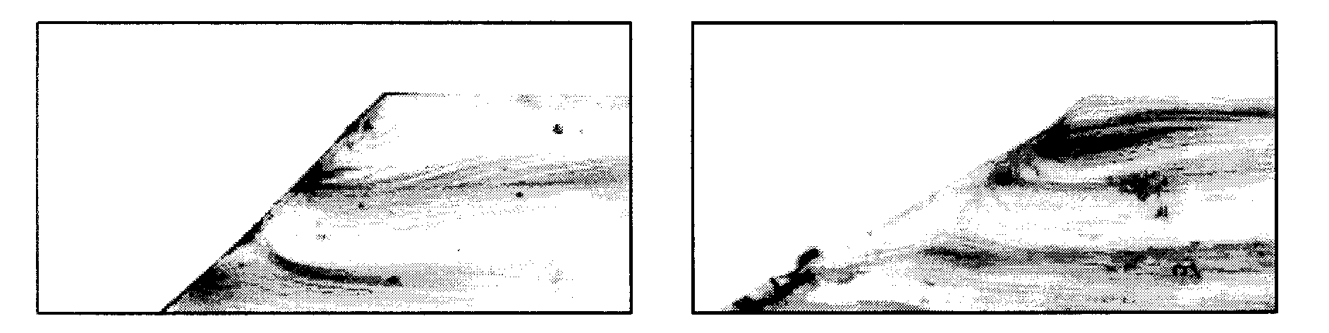
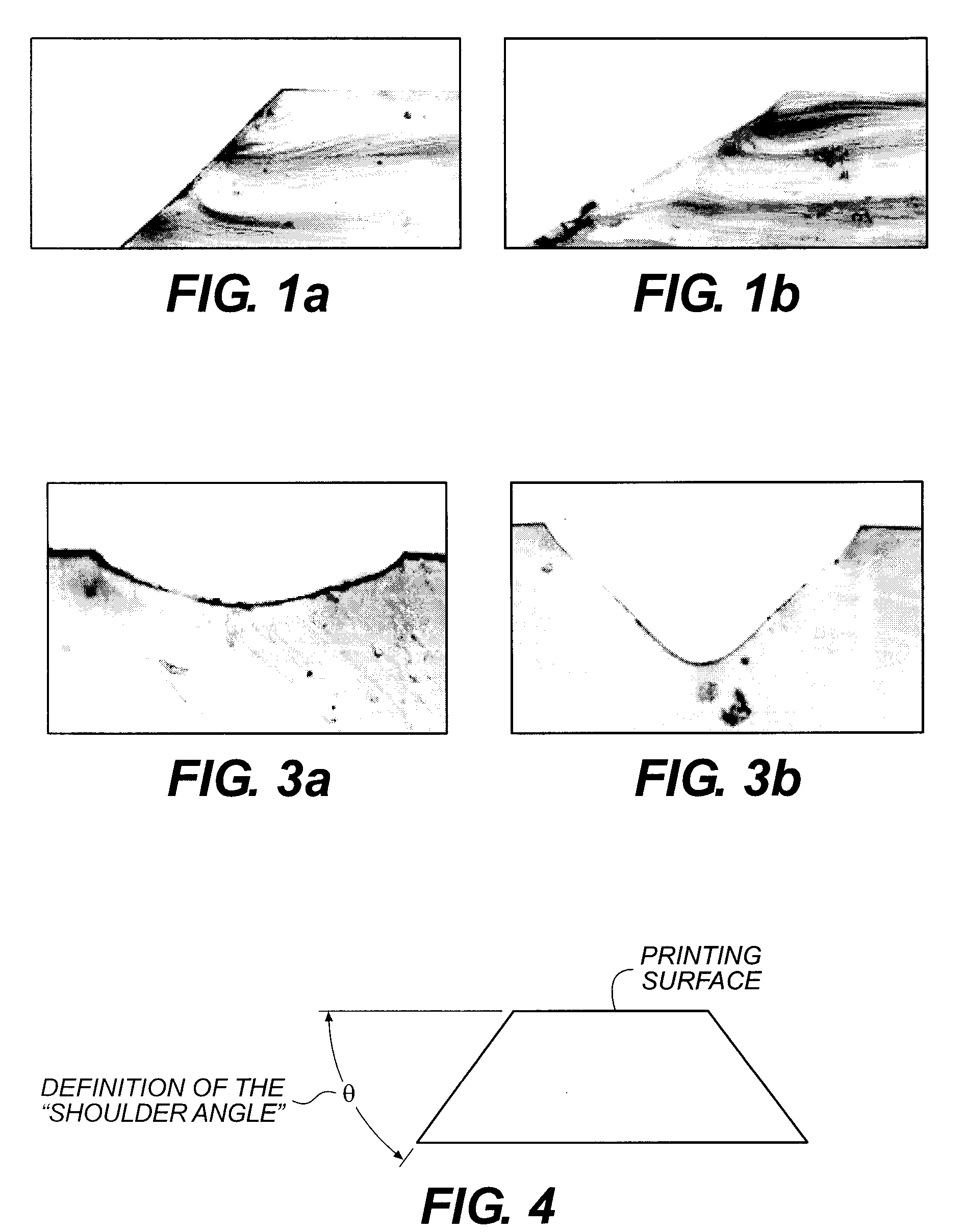
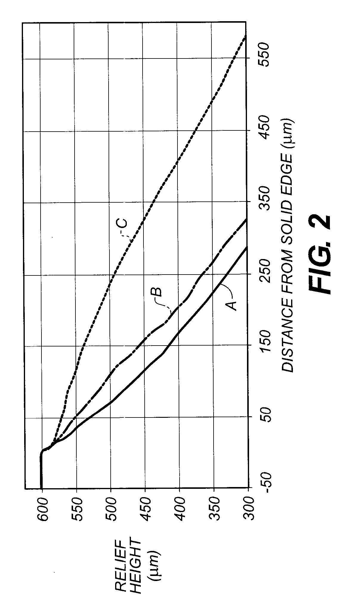
Mask film to form relief images and method of use
a mask film and relief image technology, applied in thermography, instruments, photosensitive materials, etc., can solve the problems of difficult to obtain higher sensitivity, difficult to achieve high sensitivity, and high level of halation of printed images, and achieve good reverse line depth
- Summary
- Abstract
- Description
- Claims
- Application Information
AI Technical Summary
Benefits of technology
Problems solved by technology
Method used
Image

Examples
invention example 3
[0200]Transparent layer formulations were prepared using the components shown in the following TABLE V and then used to prepare film samples.
TABLE VFilm Sample 1Film Sample 2Film Sample 3FormulationFormulation (%Formulation (%Formulation (%Componentsolids)solids)solids)Airvol ® 205908478polyvinyl alcoholPEG 600101010polyethylene glycolNaBF4 0 612n-Propanol20 parts20 parts20 partsWater80 parts80 parts80 partsPEG 600 and NaBF4 are available from Aldrich Chemical Company.
[0201]Each of the film samples above were prepared by coating the transparent layer formulations shown in TABLE V and onto 4 mil (0.01 cm) poly(ethylene terephthalate) support (carrier sheet) using a #26 wound-wire coating rod. The resulting transparent layers were dried at 93° C. for 2 minutes to provide a dry coverage of about 3.5 g / m2. Fully functional film constructions were prepared by coating and drying on each of these transparent layers: (i) barrier, (ii) imageable, and (iii) overcoat layers as described for In...
PUM
 Abstract
Description
Claims
Application Information