Premix Combustion Methods, Devices and Engines Using the Same

a combustion method and combustion engine technology, applied in the direction of machines/engines, liquid fuel feeders, electric control, etc., can solve the problems of releasing all the heat energy and damaging the engine, and achieve the effect of less penetration strength, faster combustion, and higher penetration strength

Inactive Publication Date: 2008-12-25
HOU DEYANG
View PDF25 Cites 19 Cited by
  • Summary
  • Abstract
  • Description
  • Claims
  • Application Information

AI Technical Summary

Benefits of technology

[0007]The innovative design of said combustion method and devices has solved early injection wall-wetting issues through providing a variable spray angle, which is smaller for early injection and becomes larger for late injection, and a variable spray pattern, which is soft hollow conical mist-like spray for early injection with less penetration strength, and becomes multi-jet for late injection with higher penetration strength.
[0008]The said combustion method here proposed uses a novel combustion chamber design, which divides the combustion reaction space into a plural number of smaller spaces, which has more constrains for reaction radical paths and pressure rise rate before top dead center (TDC). After TDC, the constrained reaction zone can join together, so faster combustion is enabled with a premixed charge to both improve combustion efficiency and reduce emissions.
[0009]A premixed charge of fuel and air is desirable for reducing emissions. However, for high engine loads, if all fuel and air is premixed before TDC, in the event of out of controlled combustion before TDC, the sudden release of all the heat energy could damage the engine. Thus, at high engine loads, only partially premix fuel and air before TDC is desirable. At the same time, in order to reduce emissions, an on-going ‘premixing’ process is desired. Thus, a novel method for introducing fuel into the combustion chamber space is desired to distribute certain amount of fuel in desirable locations and prepare the fuel as premixed charge to join faster combustion reaction only after TDC. This innovative method is realized by distributing fuel on the chamber surface uniformly in the format of very small discrete fuel droplets (micro-dew format) approximately in the middle stage of compression stroke. Since fuel distributed in micro-dew format needs longer time to evaporate, majority of the fuel will join faster reaction after TDC. But since the fuel in micro-dew format is formed by uniform distribution of micro droplets, after mixture ignition in combustion chamber space, the micro-dew fuel still can quickly evaporated and become vapor to join faster reaction, thus it reduces conventional diffusion combustion. This innovative discrete micro-dew distribution is unlike pooled fuel film on surface, which may produce pool fire and soot formations and should be avoided. This method solves the contradiction of making fuel premixed and controlling high pressure rise rate. This method of distributing fuel turns the ‘premixed’ combustion into ‘premixed’ plus ‘premixing’ combustion. In another word, it turns into a desirable premixed combustion into a pre-conducted and on-going mixture forming process without the limitation of excessive pressure rise concerns, at the same time, eliminated or substantially reduced diffusion combustion, thus reduce soot and NO sub(x) emissions.
[0010]By introducing fuel both with early injection and late injection with adaptive means in the same power cycle, we can produce a adaptive mixed-mode combustion, or adaptive PCCI combustion. In the adaptive PCCI, early PCCI is used to generate in-cylinder radicals to accelerate diffusion combustion and reduce NO sub (x), while accelerated diffusion combustion is used to consume CO and HC produced by PCCI and stabilize combustion. Thus, adaptive PCCI gains significantly enhanced engine efficiency and clean in-cylinder combustion simultaneously.

Problems solved by technology

However, for high engine loads, if all fuel and air is premixed before TDC, in the event of out of controlled combustion before TDC, the sudden release of all the heat energy could damage the engine.

Method used


Image

  • Premix Combustion Methods, Devices and Engines Using the Same
  • Premix Combustion Methods, Devices and Engines Using the Same
  • Premix Combustion Methods, Devices and Engines Using the Same

Examples


Embodiment Construction

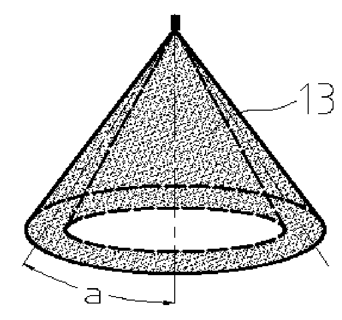
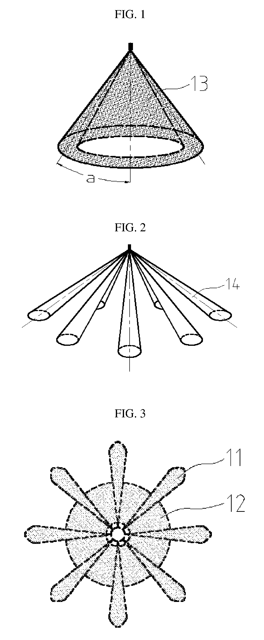
[0021]A method of combustion, comprising steps of: (i) determining fuel injection timings by engine speed, fuel injection quantity, (ii) utilizing a fuel injector composing a variable injection orifice, (iii) varying injection spray angles based upon injection timing, wherein spray angles increase with late injection timing and decrease with early injection timing relative to engine top dead center, (iv) varying spray patterns wherein spray patterns tend toward hollow conical shapes with determined early injection timings, and tend toward a multi-jet shape with determined late injection timings, (v) wherein distributing fuel into combustion chamber space and surface with adaptive means based on injection quantity and injection timings, thus enable a mixed-mode premixed and conventional combustion.

[0022]As shown in FIG. 8, the spray pattern can vary along with injection timings through controlling the nozzle needle lift; spray patterns can be varied from hollow conical spray with sma...


PUM


Abstract

This invention discloses a combustion method, which is for internal combustion engine, which utilizes a variable spray fuel injection wherein it has (i) a variable spray angle with smaller angles for earlier fuel injection and larger angles for later fuel injection, and (ii) variable spray patterns varying from hollow conical shapes for earlier injection to multi-jet shapes for later injection, wherein it has adaptive means to distribute fuel into combustion chamber space based on background pressure and injection timing. A combustion method, which utilizes a combustion chamber which has plural number of annular inner spaces resembling the space inside an automotive tire, which provides means to control propagation paths of combustion reaction radicals and control pressure rise rate, which also provides means to promote stratification of premixed charges. An internal combustion engine utilizing the said combustion methods is also disclosed.

Description

CROSS-REFERENCE TO RELATED APPLICATION[0001]This application is based on and claims priority to U.S. Provisional Application No. 60945583, filed on Jun. 21, 2007, and the disclosures of each are incorporated herein by reference.BACKGROUND OF THE INVENTION[0002]1. Field of the Invention[0003]The present invention relates to combustion methods, devices, and an internal combustion engine using the same, either compression ignition or spark ignition internal combustion engines.[0004]2. Description of the Related Art[0005]While the engine industries have put great efforts for Homogenous Charge Compression Ignition (HCCI) and Premixed Charge Compression Ignition (PCCI) PCCI combustion, the conventional multi-hole fuel injector limits the operation ranges of HCCI and PCCI. The major reasons are due to the fixed injection angle and dense jet nature of conventional sprays. Since currently HCCI or PCCI can only operate in low to medium loads in practical applications, conventional fixed-area ...

Claims


Application Information

Patent Timeline
Patent Type & Authority Applications(United States)
IPC IPC(8): F02M69/04
CPCF02B1/12Y02T10/128F02B23/0669F02B23/0672F02B23/101F02B2023/103F02B2075/125F02B2275/14F02D41/047F02D41/3035F02D41/402F02M45/02F02M61/161F02M61/1813Y02T10/125Y02T10/123F02B17/005Y02T10/12
Inventor HOU, DEYANG
Owner HOU DEYANG
Why Eureka
Try Eureka