Method for producing conductive thermoplastic elastomer composition and conductive roller composed of same

a technology of conductive thermoplastic elastomer and composition, which is applied in the direction of conductive materials, non-conductive materials with dispersed conductive materials, electrography/magnetography, etc., can solve the problems of difficult moldability of electroconductive polymer composition, inability to recycle, and difficulty in controlling the electric resistance of the conductive roller, so as to reduce the variation of the electric resistance of the conductive thermoplastic elastomer composition, the effect of suppressing the increase of the compression s

Inactive Publication Date: 2008-12-25
SUMITOMO RUBBER IND LTD
View PDF5 Cites 39 Cited by
  • Summary
  • Abstract
  • Description
  • Claims
  • Application Information

AI Technical Summary

Benefits of technology

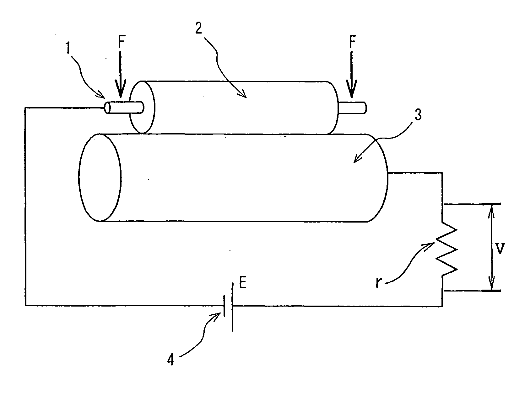
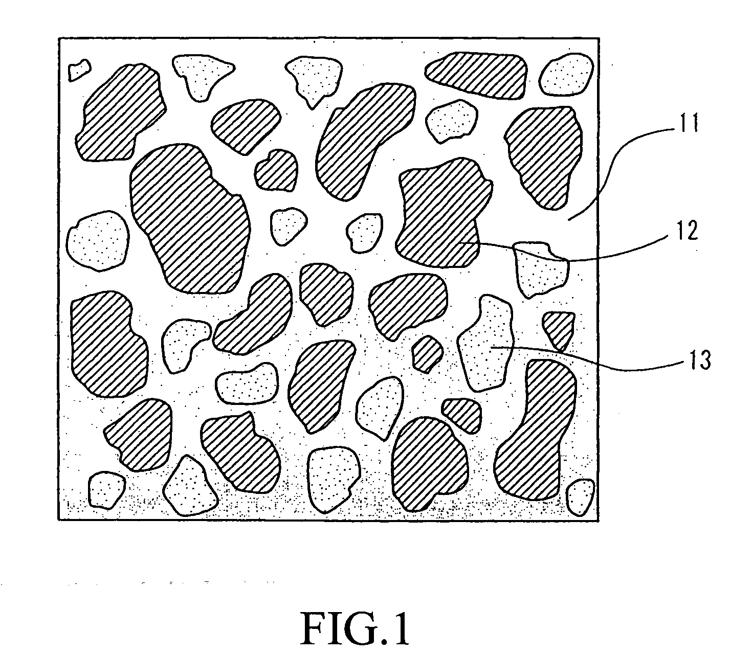
[0175]In the conductive thermoplastic elastomer composition of the present invention, the rubber component (B) containing at least one of the diene rubber and the ethylene-propylene-diene rubber is dynamically crosslinked in the mixture (component A) of the thermoplastic elastomer and the thermoplastic resin. Therefore the conductive thermoplastic elastomer composition is provided with rubber-like durability, elasticity, and flexibility and resin-like moldability. Further the composition of the present invention is thermoplastic and can be recycled.
[0176]In addition, because the rubber component (component B) independently forms the uncontinuous phase, the crosslinking degree of the rubber is not affected by the component (C), although the component (C) is dispersed in the component (A). Consequently it is possible to suppress an increase of the compression set because the crosslinking degree does not become low and in addition the electric resistance of the conductive thermoplastic elastomer composition can be effectively decreased. Further the conductive thermoplastic elastomer composition has a proper degree of hardness, does not pollute a photosensitive member, and is capable of decreasing the variation of the electric resistance thereof.
[0177]The conductive roller produced by mixing micro-capsules each containing the acrylic group-containing polymer as its outer shell with the conductive thermoplastic elastomer composition and extruding the mixture is capable of keeping a low hardness even in a low-temperature environment. Therefore an image-forming apparatus where the conductive roller is mounted is capable of forming preferable images without causing defective transfer, defective charge, and defective transport at a low temperature. When the particle diameter of the micro-capsule is not less than 100 μm nor more than 500 μm, it is not necessary to sacrifice the processability to decrease the hardness of the conductive thermoplastic elastomer composition, but preferable moldability can be achieved.

Problems solved by technology

Thus it is very difficult to control the electric resistance of the conductive roller.
In addition, because it is difficult to uniformly disperse the conductive filler in the polymer, the electric resistance value has variations in the circumferential and widthwise directions of the conductive roller.
Further when the electroconductive polymer composition contains a very large amount of the conductive filler such as the carbon black, it is difficult to mold the electroconductive polymer composition.
The conductive roller using the electroconductive polymer composition has the above-described problems.
But the vulcanized rubber composition is not thermoplastic and cannot be recycled.
When a conventional ionic-conductive agent is used, it is difficult to effectively decrease the electric resistance of the conductive roller.
When a large amount of the ionic-conductive agent is contained in the polymer composition to solve this problem, bleeding occurs and mechanical properties such as the compression set, hardness, and the like of the composition composing the conductive roller deteriorate.
When the electric resistance value changes greatly at the time of a continuous application of a voltage, a defective image is formed and so on.
That is, it is impossible to reliably maintain the image quality.
But the hardness of the conductive roller is a little high when it is used in a low-temperature environment.
Thus when the conductive roller is used as a transfer roller, the conductive roller causes a decrease in the adhesiveness of a roller to paper.
Thereby in some cases, a defective image is generated because the toner is not exactly transferred to the paper.
When the kind of the thermoplastic resin is changed to decrease the hardness of the conductive polymer composition so that the problem of the generation of the defective image in the low-temperature environment is solved, the processability of the conductive polymer composition is liable to deteriorate.
Thus it is difficult to improve the generation of the defective image in the low-temperature environment.

Method used


Image

  • Method for producing conductive thermoplastic elastomer composition and conductive roller composed of same
  • Method for producing conductive thermoplastic elastomer composition and conductive roller composed of same
  • Method for producing conductive thermoplastic elastomer composition and conductive roller composed of same

Examples


example 1

[0230]The thermoplastic elastomer and the thermoplastic resin (component A), the EPDM rubber (component B), the softener, and the crosslinking agent were mixed with one another at the ratio shown in table 1 shown below. Thereafter the components were fused and kneaded at 200 rpm and 200° C. by using a twin-screw extruder (“HTM 38” produced by I-pec Inc.). After the component (B) was dynamically crosslinked with the crosslinking agent and extruded with the component (B) being dispersed in the component (A), the mixture was pelletized to obtain an elastomer composition (I).

[0231]The obtained pelletized elastomer composition (I), the EO-PO-AGE copolymer and the anion-containing salt having the fluoro group and the sulfonyl group (component C), the crosslinking agent, and the compatibilizing agent were mixed with one another at the mixing ratio shown in table 1 shown below. After the components were fused and kneaded at 200 rpm and 200° C. by using the twin-screw extruder (“HTM 38” prod...

examples 2 through 4 and 6 through 10

[0265]The thermoplastic elastomer and the thermoplastic resin (component (A)), the pelletized EPDM rubber (component B), the softener, a crosslinking agent 2, and zinc white were mixed with one another at the ratio shown in table 2 shown below. Thereafter the components were fused and kneaded at 200 rpm and 200° C. by using the twin-screw extruder (“HTM 38” produced by I-pec, Inc.). After the component (B) was dynamically crosslinked with the crosslinking agent and extruded, with the component (B) being dispersed in the component (A), the mixture was pelletized to obtain the elastomer composition (I).

[0266]The obtained pelletized elastomer composition (I), the EO-PO-AGE copolymer and the anion-containing salt having the fluoro group and the sulfonyl group (component (C)), the crosslinking agent 1, and the compatibilizing agent were mixed with one another at the mixing ratio shown in table 2 shown below. After the components were fused and kneaded at 200 rpm and 200° C. by using the ...

example 5

[0269]Except that the conductive thermoplastic elastomer composition did not contain the micro-capsule, the conductive roller was obtained by carrying out a method identical to that of the example 1.


PUM

PropertyMeasurementUnit
temperatureaaaaaaaaaa
diameteraaaaaaaaaa
diameteraaaaaaaaaa

Abstract

A conductive thermoplastic elastomer composition including a continuous phase and first and second uncontinuous phases. The continuous phase and the first and second uncontinuous phases form a sea-island structure; and the first and second uncontinuous phases independently forming island structures. In this structure, the continuous phase contains a composition (A) which is a mixture of a thermoplastic elastomer and a thermoplastic resin; the first continuous phase contains a rubber component (B) containing at least one of diene rubber and ethylene-propylene-diene rubber; and the second continuous phase contains an ethylene oxide-propylene oxide-allyl glycidyl ether copolymer containing an anion-containing salt having a fluoro group and a sulfonyl group (component (C)).

Description

[0001]This non-provisional application claims priority under 35 U.S.C. § 119(a) on Patent Application No(s). 2007-155152 filed in Japan on Jun. 12, 2007, the entire contents of which are hereby incorporated by reference.BACKGROUND OF THE INVENTION[0002]1. Field of the Invention[0003]The present invention relates to a method of producing a conductive thermoplastic elastomer composition, and a conductive roller composed of the conductive thermoplastic elastomer composition and more particularly to a conductive roller useful as a transfer roller mounted in an image-forming apparatus.[0004]2. Description of the Related Art[0005]It is necessary for the conductive roller mounted in an image-forming apparatus such as a transfer roller, a driving roller, a developing roller, a charging roller, and the like to have a proper and stable electric resistance value.[0006]As conventional methods of imparting conductivity to the conductive roller of this kind, the following two methods are conventi...

Claims


Application Information

Patent Timeline
Patent Type & Authority Applications(United States)
IPC IPC(8): H01B1/12F16C13/00B29C48/40B29C48/92
CPCB29C47/0004B29C47/92B29K2021/00B29K2023/16C08G65/14C08G2650/58C08K5/14C08K5/42C08K5/43C08L21/00C08L23/0869C08L23/10C08L23/16C08L53/02C08L71/00C08L71/02C08L101/10C08L2205/035C08L2205/05C08L2312/00G03G15/0808G03G15/0818G03G21/0058G03G2215/00957G03G2215/1614H01B1/122H01B1/24B29C47/0009C08L2666/06C08L2666/02C08L2666/04B29C48/92B29C2948/92704B29C48/022B29C48/03B29C48/40B29C2948/92047B29C2948/92428B29C2948/92523B29C2948/92733B29C2948/92895B29C2948/92923
Inventor MINAGOSHI, AKIRA
Owner SUMITOMO RUBBER IND LTD
Why Eureka
Try Eureka