
Method and Arrangement for Generating and Controlling a Discharge Plasma

a technology of discharge plasma and control arrangement, which is applied in the direction of electric variable regulation, process and machine control, instruments, etc., can solve the problems that the low current density varieties cannot follow the fast displacement current variation, and achieve the effect of improving the controllability of the plasma breakdown

Inactive Publication Date: 2008-12-25
FUJIFILM MFG EURO
View PDF61 Cites 36 Cited by
  • Summary
  • Abstract
  • Description
  • Claims
  • Application Information

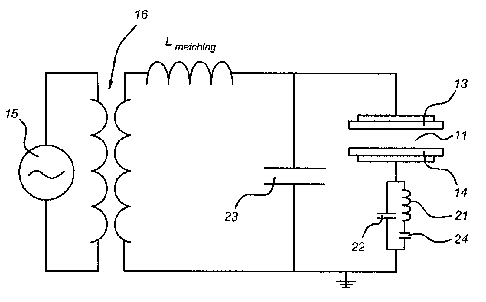
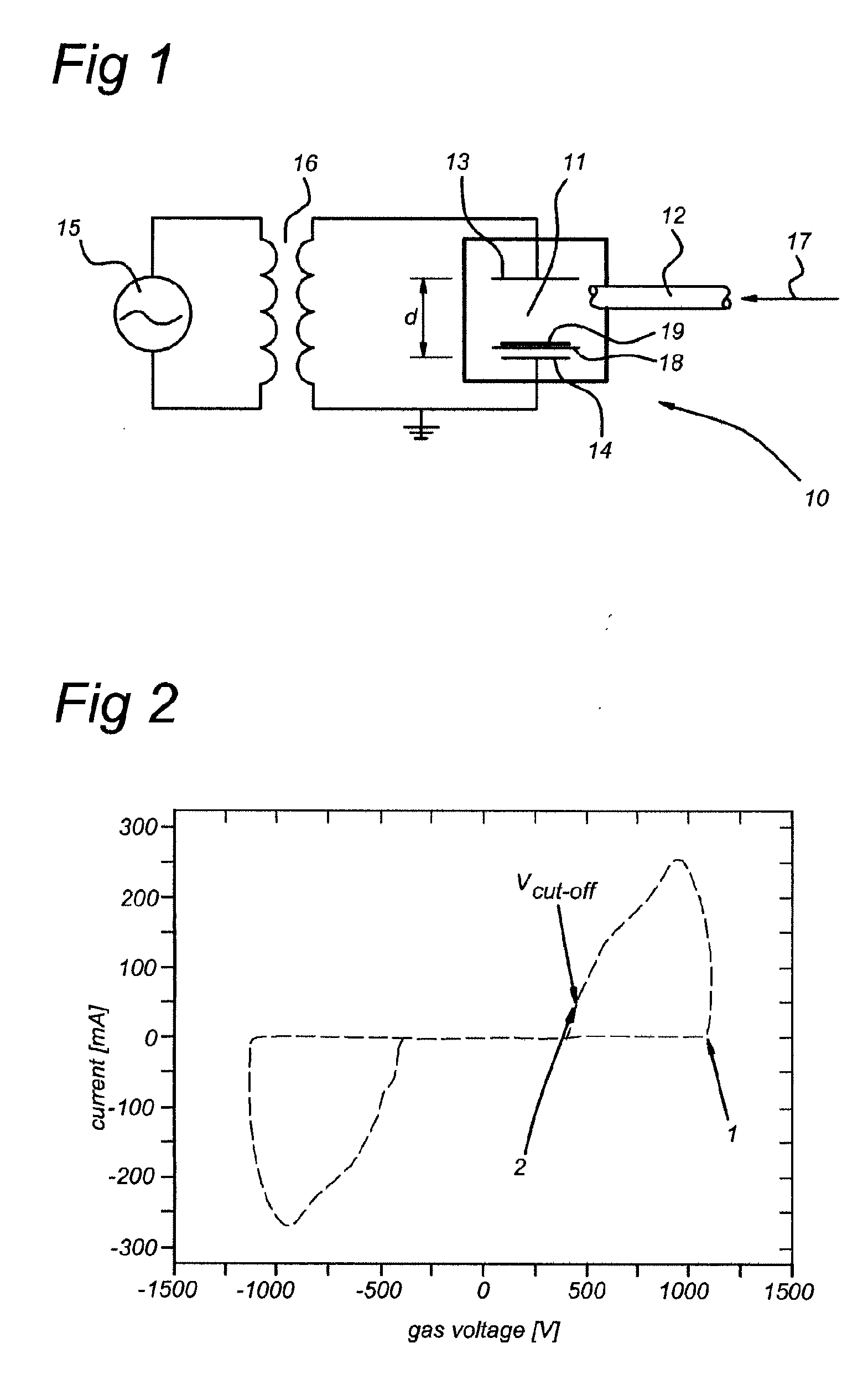
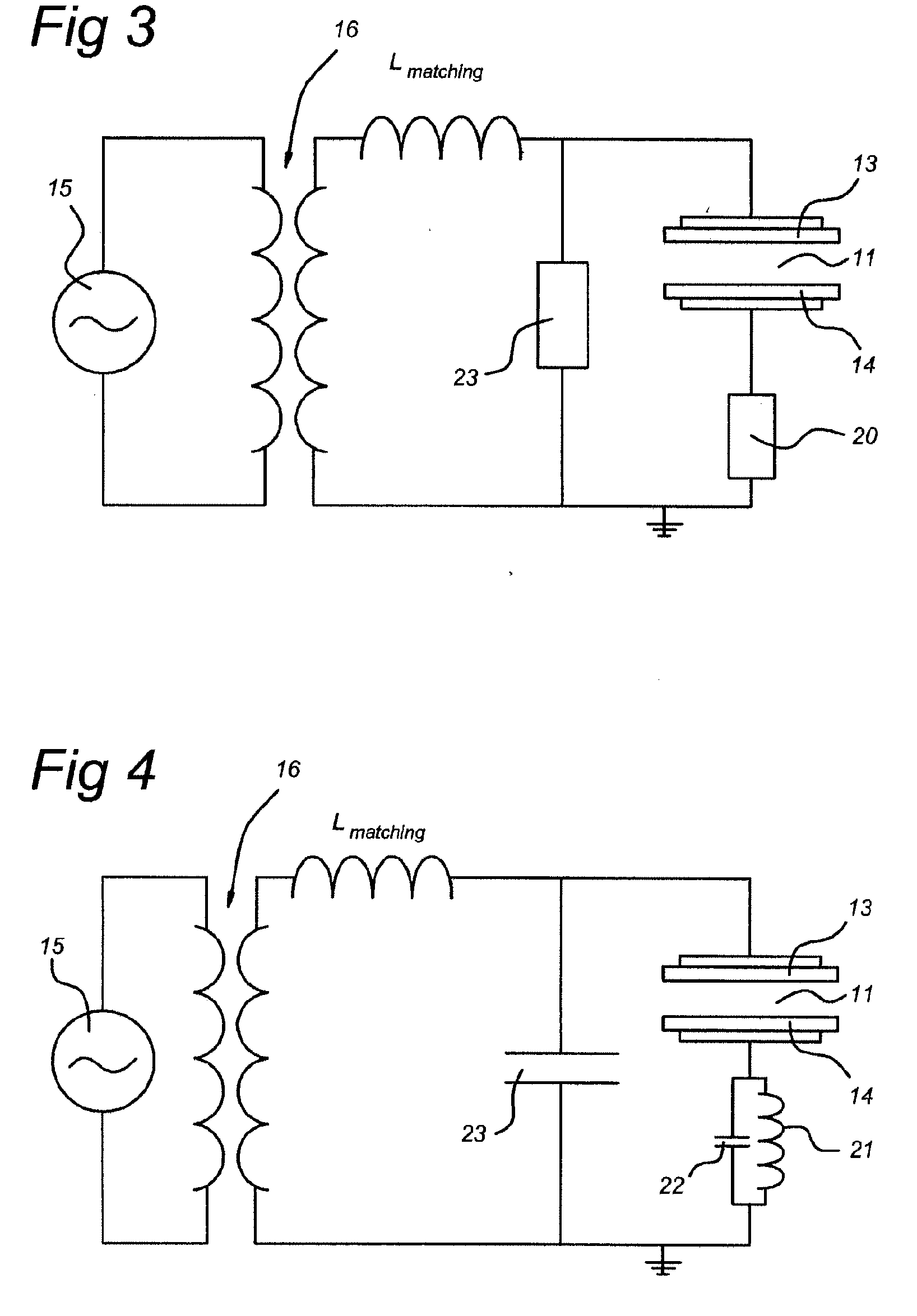
AI Technical Summary

Benefits of technology

[0010]The present invention seeks to provide a method and arrangement for controlling an APG plasma with improved controllability of the plasma breakdown and ability to provide a very uniform glow discharge.
[0011]According to the present invention, a method according to the preamble deftned above is provided, in which controlling the discharge comprises applying a displacement current with a rate of change d / Ildt for controlling local current density variations associated with a plasma variety having a low ratio of dynamic to static resistance. The low ratio of dynamic to static resistance (r / R) is e.g. equal to or lower than 0.1, Plasma varieties having a low ratio of dynamic to static resistance are e.g. filamentary plasmas, which are characterized by local perturbation of current density (e.g. in areas as small as 10 μm2). A glow plasma is characterized by a relatively high dynamic to static resistance, having a value around 1. The capacitive impedance of at least one of the electrodes may be provided by a dielectric barrier electrode, or as a capacitor in series with the electrode. Also, in operation a plasma sheath may be formed when using two metal electrodes, which also provides the capacitive impedance. The tendency of a plasma of having a larger or smaller current density is reflected in its dynamic resistance. The plasma current density will follow a relative rate of change of displacement current dI / Idt with a certain delay time which is independent of the area of perturbation. Thus, even local current density variations are individualized by their respective dynamic resistance. This means that even very locally the current of large density varieties (filaments) will closely follow even fast variations of the displacement current so they can be boosted or damped. The lower current density varieties will not be able to follow the fast displacement current variations. In this way the control of temporal and spatial density of filaments may be controlled by the displacement current. Even very local perturbations having a low ratio of dynamic to static resistance which can not be detected by any electronics can be controlled in this way. More generally the probability of formation of varieties of a current density is controlled by the variation of displacement current during plasma generation. The present method thus offers a solution to control locally the probability of formation of high current density varieties (filaments), for any plasma. The present method may be used to control the characteristic of the generated atmospheric pressure plasma. It may be used to suppress any unwanted instabilities in order to obtain a glow discharge plasma with a high as possible uniformity. On the other hand, the present method may also be used to stimulate the occurrence of filamentary discharges, e.g. useable for generating ozone in an atmospheric environment.
[0012]In the present control method and arrangement for controlling instabilities, two stages of a plasma generation may be specifically controlled using a single control method. In this embodiment, the displacement current rate change is applied at least at the breakdown of a plasma pulse. By suppressing instabilities at least at this stage, no filamentary discharges can develop, and a stable glow discharge plasma is formed. Furthermore, the displacement current rate of change may additionally be applied also at the cut-off of the plasma pulse, to provide an even better suppression of instabilities. The displacement current rates of change may be applied using fast relative variations of displacement current.

Problems solved by technology

The lower current density varieties will not be able to follow the fast displacement current variations.

Method used


Image

  • Method and Arrangement for Generating and Controlling a Discharge Plasma
  • Method and Arrangement for Generating and Controlling a Discharge Plasma
  • Method and Arrangement for Generating and Controlling a Discharge Plasma

Examples


examples

[0082]The present method and control arrangement have been used in an experimental set-up for treating the surface of a polymer material.

[0083]Standard APG systems operating at atmospheric pressure using Ar and N2 or pure N2 are very unstable and therefore not suitable for industrial applications. Furthermore, the power density's applied in the APG plasma (typically <<1 W / cm2) are lower than in corona equipment (up to 6 W / cm2). Increasing the excitation frequency enhances the power density (effectiveness) of the plasma, however, under normal conditions the discharge becomes Localized in streamers which decreases the homogeneity of the treatment very much.

[0084]In the present atmospheric pressure dielectric barrier discharge (DBD) set-up an APG plasma is generated at a high frequency (HF) using Ar—N2 mixtures or pure nitrogen where the plasma stability is controlled by controlling the displacement current (by using a dedicated matching network) which provides a very strong and unifor...


PUM


Abstract

Method and arrangement for controlling a discharge plasma in a discharge space (11) having at least two spaced electrodes (13, 14). A gas or gas mixture is introduced in the discharge space (11), and a power supply (15) for energizing the electrodes (13, 14) is provided for applying an AC plasma energizing voltage to the electrodes (13, 14). At least one current pulse is generated and causes a plasma current and a displacement current. Means for controlling the plasma are provided and arranged to apply a displacement current rate of change for controlling local current density variations associated with a plasma variety having a low ratio of dynamic to static resistance, such as filamentary discharges. By damping such fast variations using a pulse forming circuit (20), a uniform glow discharge plasma is obtained.

Description

FIELD OF THE INVENTION[0001]The present invention relates in general to a method and control arrangement for generating and controlling a discharge plasma, such as a glow discharge plasma. More in particular, the present invention relates to a method for controlling a discharge plasma in a gas or gas mixture, in a plasma discharge space having at least two spaced electrodes, in which at least one current pulse is generated by applying an AC plasma energizing voltage to the electrodes causing a plasma current and a displacement current. In a further aspect the present invention relates to an arrangement for generating and controlling a discharge plasma in a discharge space having at least two spaced electrodes, means for introducing a gas or gas mixture in the discharge space, a power supply for energizing the electrodes by applying an AC plasma energizing voltage to the electrodes for generating at least one current pulse and causing a plasma current and a displacement current, and ...

Claims


Application Information

Patent Timeline
Patent Type & Authority Applications(United States)
IPC IPC(8): B01J19/08H05B41/36H01J7/24
CPCH05H2240/10H05H1/46H05H2001/466H05H2001/4682H05H1/466H05H2242/26
Inventor DE VRIES, HINDRIK WILLEMALDEA, EUGENBOUWSTRA, JAN BASTIAANVAN DE SANDEN, MAURITIUS CORNELIUS MARIA
Owner FUJIFILM MFG EURO
Learn More