Honeycomb structure and method for manufacturing honeycomb structure

a technology of honeycomb and honeycomb, which is applied in the direction of machines/engines, chemical/physical processes, solid waste management, etc., can solve the problems of construction machines raising serious problems, and contaminants harmful to the environment and the human body

Active Publication Date: 2008-12-25
IBIDEN CO LTD
View PDF101 Cites 101 Cited by
  • Summary
  • Abstract
  • Description
  • Claims
  • Application Information

AI Technical Summary

Problems solved by technology

In recent years, particulate matter (hereinafter, also referred to as “PM”) such as soot contained in exhaust gases discharged from internal combustion engin

Method used


Image

  • Honeycomb structure and method for manufacturing honeycomb structure
  • Honeycomb structure and method for manufacturing honeycomb structure
  • Honeycomb structure and method for manufacturing honeycomb structure

Examples


first embodiment

[0075]The following will discuss a first embodiment, which is one embodiment of the present invention, with reference to drawings.

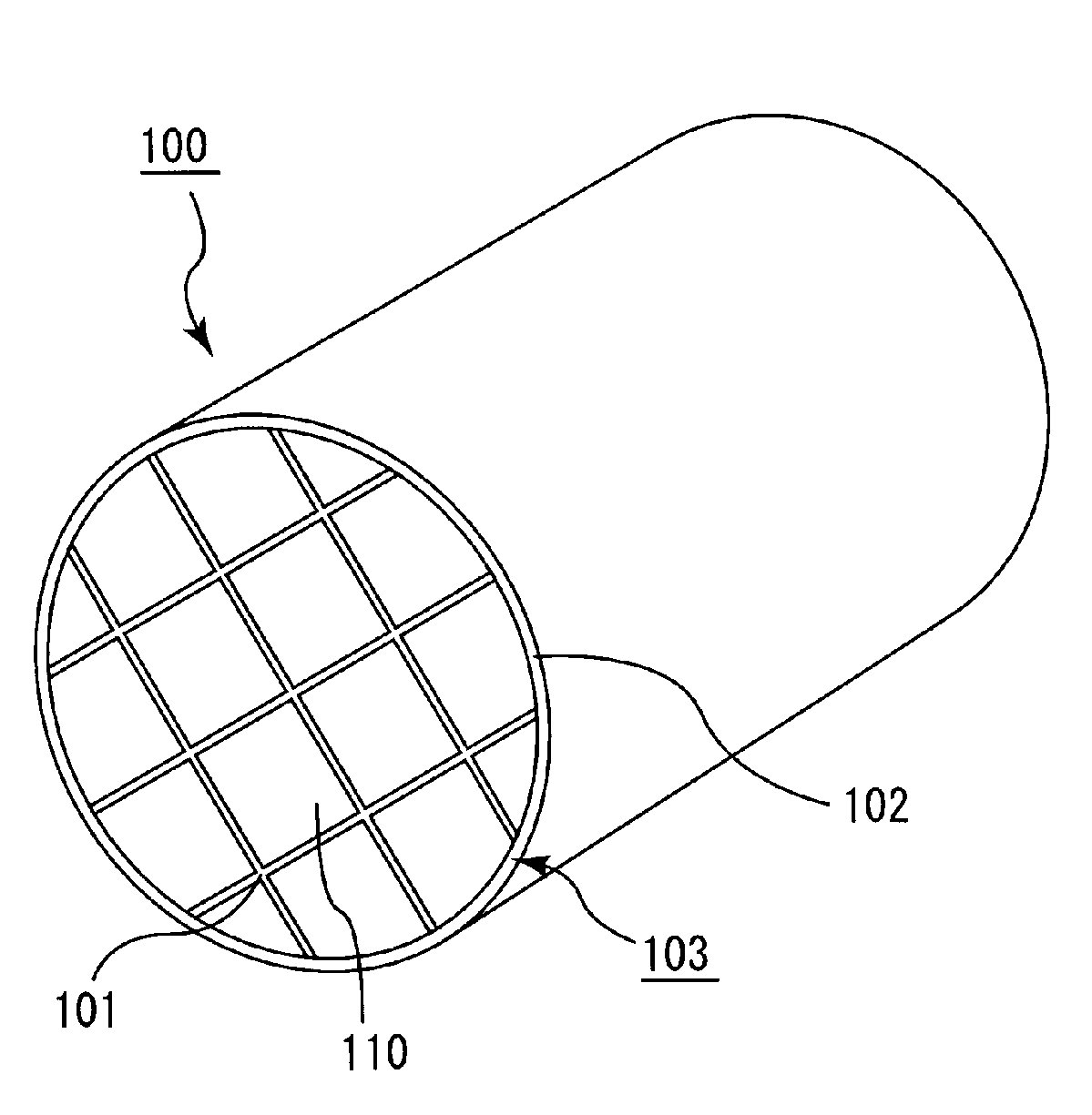
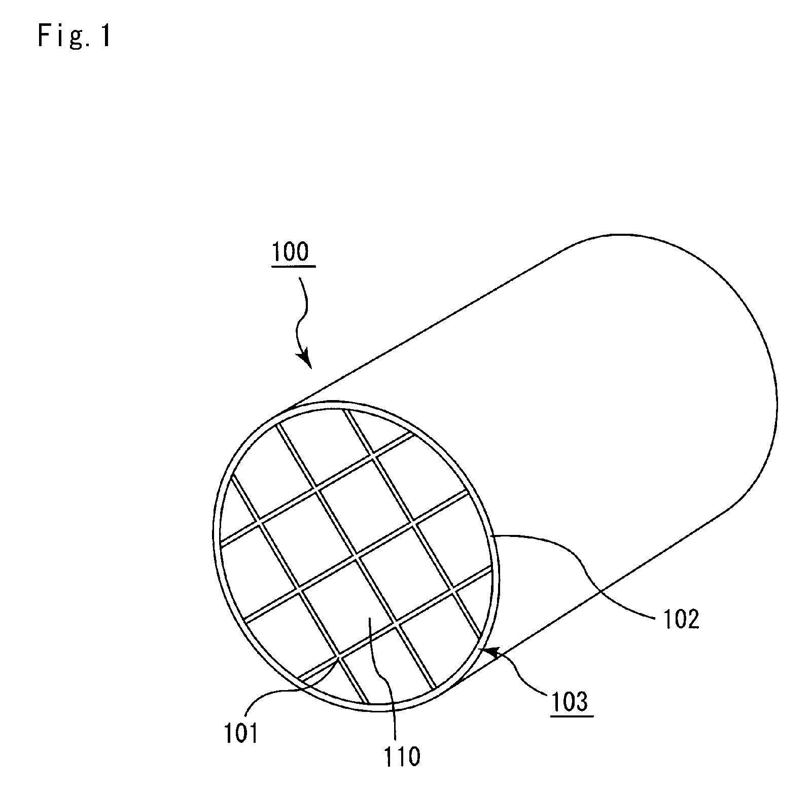
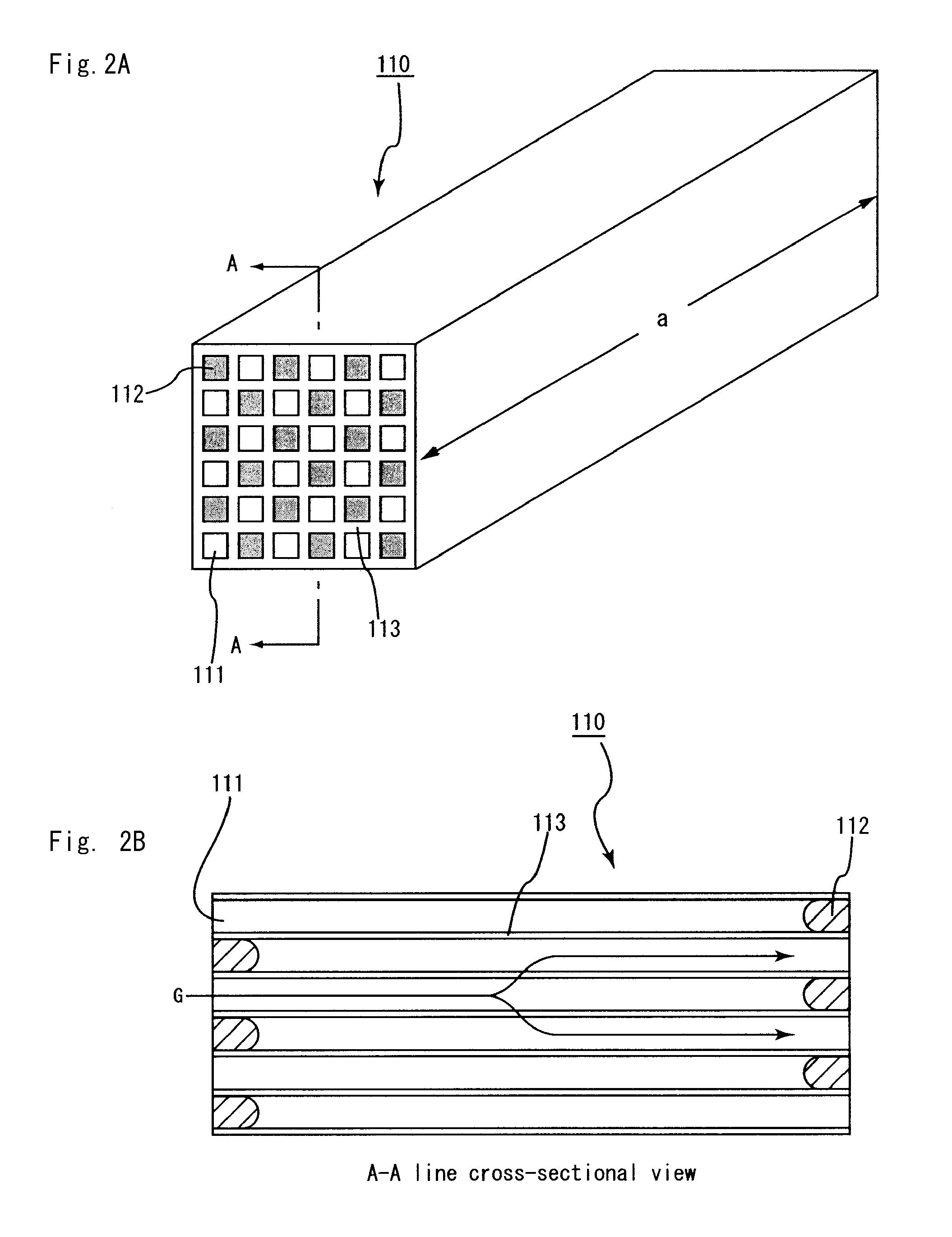
[0076]FIG. 1 is a perspective view schematically showing one example of the honeycomb structure of an embodiment of the present invention. FIG. 2A is a perspective view schematically showing one example of the honeycomb fired body forming the honeycomb structure of an embodiment of the present invention, and FIG. 2B is an A-A line cross sectional view of the honeycomb fired body shown in FIG. 2A.

[0077]In a honeycomb structure 100 shown in FIG. 1, a plurality of honeycomb fired bodies 110 made of porous silicon carbide, each having a shape as shown in FIGS. 2A and 2B, are bonded with one another by interposing a sealing material layer (adhesive layer) 101 to form a ceramic block 103, and a sealing material layer (coat layer) 102 is further formed on the periphery of this ceramic block 103.

[0078]In a honeycomb fired body 110 shown in FIGS. 2A and 2B, a larg...

example 1

Manufacturing of Honeycomb Fired Body

[0141]An amount of 52.8% by weight of a silicon carbide coarse powder having an average particle diameter of 22 μm and 22.6% by weight of a silicon carbide fine powder having an average particle diameter of 0.5 μm were mixed. To the resulting mixture, 2.1% by weight of an acrylic resin, 4.6% by weight of an organic binder (methylcellulose), 2.8% by weight of a lubricant (UNILUB, manufactured by NOF Corporation), 1.3% by weight of glycerin, and 13.8% by weight of water were added, and then kneaded to prepare a mixed composition. The obtained mixed composition was extrusion-molded, so that a raw honeycomb molded body having virtually the same shape as the shape shown in FIG. 2A and having cells not sealed was manufactured.

[0142]Next, the raw honeycomb molded body was dried by using a microwave drying apparatus to obtain a dried honeycomb molded body. A paste having the same composition as that of the raw molded body was then filled into predetermin...

examples 2 to 5

[0158]Honeycomb structures were manufactured in the same manner as in Example 1, except for the use of cavity-holding members each manufactured by changing a composition of a raw material so as to have Young's modulus of the value shown in Table 1.


PUM

PropertyMeasurementUnit
Temperatureaaaaaaaaaa
Timeaaaaaaaaaa

Abstract

A honeycomb structure includes a ceramic block and a sealing material layer. The ceramic block includes a plurality of honeycomb fired bodies each having a large number of cells longitudinally disposed substantially in parallel with one another with a cell wall between the cells, an adhesive layer for bonding side faces of the honeycomb fired bodies, and a cavity-holding member placed between the side faces of the honeycomb fired bodies. The sealing material layer is formed on a peripheral face of the ceramic block. The cavity-holding member includes a nonflammable material having Young's modulus of at least about 0.001 GPa and at most about 0.07 GPa.

Description

CROSS-REFERENCE TO RELATED APPLICATIONS[0001]The present application claims priority under 35 U.S.C. §119 to PCT Application No. PCT / JP2007 / 062505, filed Jun. 21, 2007, the contents of which are incorporated herein by reference in their entirety.BACKGROUND OF THE INVENTION[0002]1. Field of the Invention[0003]The present invention relates to a honeycomb structure and a method for manufacturing the honeycomb structure.[0004]2. Discussion of the Background[0005]In recent years, particulate matter (hereinafter, also referred to as “PM”) such as soot contained in exhaust gases discharged from internal combustion engines of vehicles such as buses and trucks, and construction machines has raised serious problems as contaminants harmful to the environment and the human body. For this reason, a honeycomb structure including a porous ceramic, in which a plurality of honeycomb fired bodies, each having a large number of cells longitudinally disposed in parallel with one another with a cell wal...

Claims


Application Information

Patent Timeline
IPC IPC(8): B32B3/12C04B37/00
CPCB01D46/0063B01D46/2448B01D46/2451B01D46/2459B01D2279/30B28B1/002B28B7/0088B28B11/12B28B19/0015B28B19/0038C04B28/24C04B30/02C04B35/565C04B35/80C04B37/005C04B38/0006C04B38/0019C04B2111/00793C04B2111/0081C04B2111/343C04B2237/083C04B2237/34C04B2237/341C04B2237/343C04B2237/346C04B2237/348C04B2237/365C04B2237/38C04B2237/708F01N3/0222F01N3/2828F01N2450/28C04B38/0054C04B38/0074C04B14/042C04B14/08C04B14/18C04B14/20C04B14/28C04B14/303C04B14/42C04B14/46C04B18/241C04B14/324C04B14/4625C04B24/383Y02W30/97Y10T428/24149Y02W30/91B01D46/84B01D46/2482B01D46/2478B01D46/24495B01J35/04B01J35/00B01D39/00B01D53/34B01D46/2425B01D46/2455B01D46/249B01D46/2466
Inventor SAKAKIBARA, KAZUAKI
Owner IBIDEN CO LTD
Why Eureka
Try Eureka