Process and method for the removal of arsenic from water

a technology of arsenic and water, applied in water/sludge/sewage treatment, water contaminants, filtration treatment, etc., can solve the problems of high cost, high cost, and high pollution of primary water, and achieve the effect of very efficiently trivalent removal

Inactive Publication Date: 2009-01-08
DEL SIGNORE GIOVANNI
View PDF2 Cites 27 Cited by
  • Summary
  • Abstract
  • Description
  • Claims
  • Application Information

AI Technical Summary

Problems solved by technology

Any pollutant removal process, therefore also arsenic remediation from water, has to face the main problem of the disposal of the by-products produced from said processes.
Reverse Osmosis (RO) has a high removal efficiency but has the drawback that the primary water becomes highly polluted, with concentrations even higher than the water before treatment.
Electrodyalisis presents nearly the same problems of the RO process, with higher costs.
Moreover the spent Alumina presents disposal problems during its regeneration.

Method used


Image

  • Process and method for the removal of arsenic from water
  • Process and method for the removal of arsenic from water

Examples


experimental examples

Example N.1

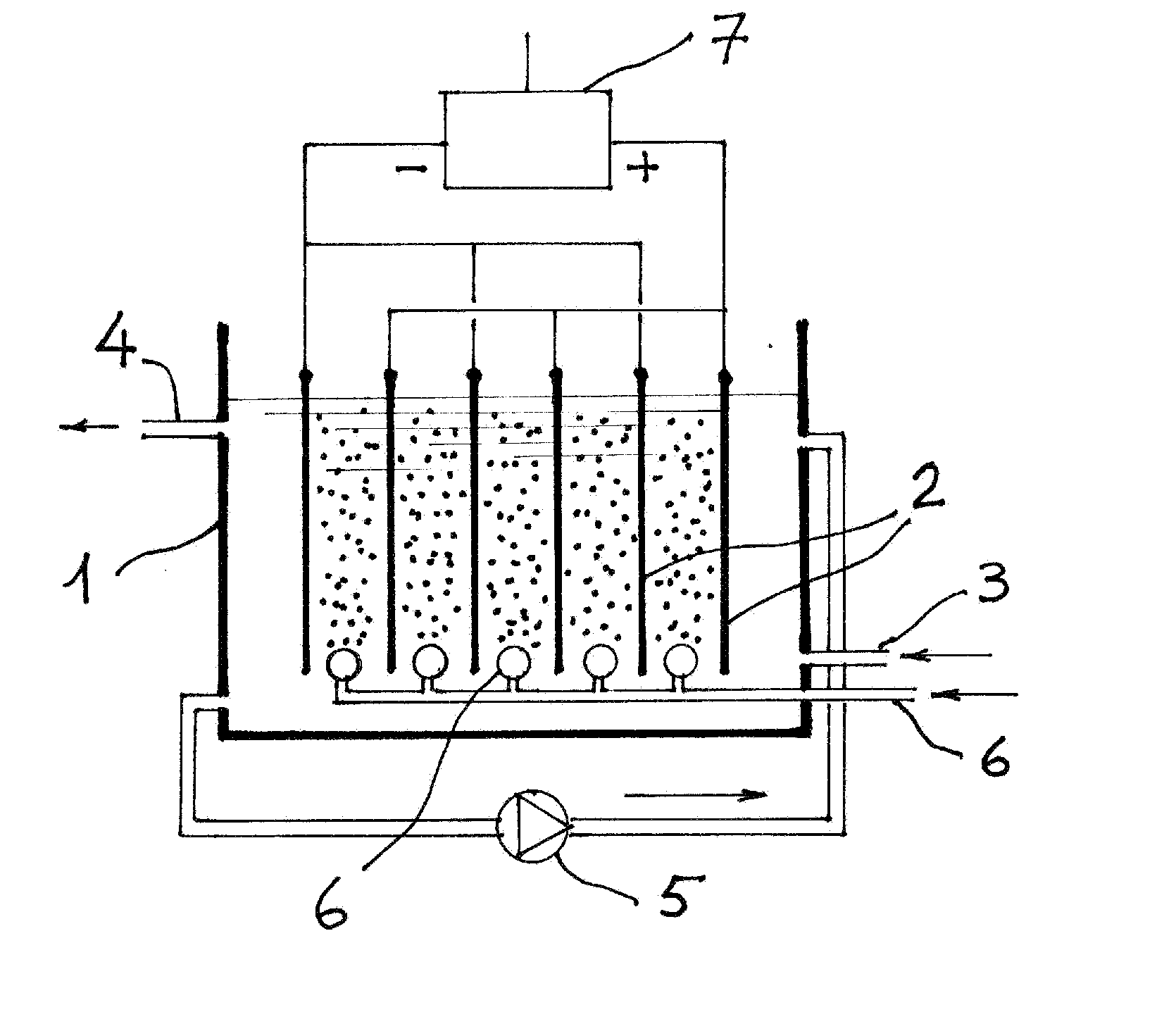
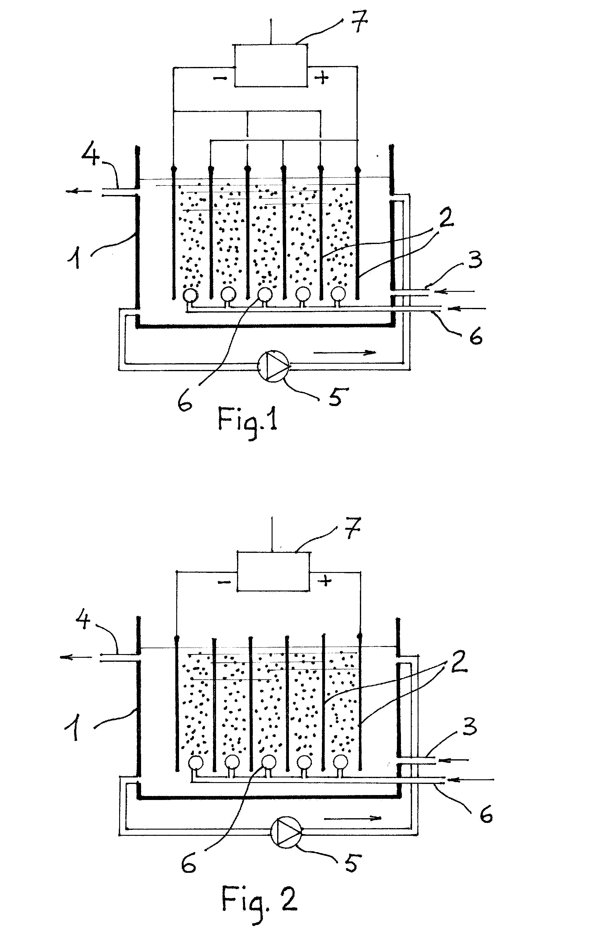
[0040]An electrolytic cell was assembled as illustrated in FIG. 1. The electrodes were obtained from commercial mild steel sheet. The anode measured 3.5×7 cm. Facing two identical cathodes of the same size. The resulting active area was therefore 49 cm2. The gap between anode and the two cathodes was 4.0 mm. The electrodes were place vertically in an insulating container. At the base and under the electrodes a ceramic porous candle was placed and connected by means of a flexible plastic tube and flow meter to a compressed air supply. The test water to be spiked with arsenic had the following characteristic:

[0041]pH=7.08; hardness=49.3° F.; conductivity=590 μS; D.O.=5.6 mgL−1 at 17.6° C.;

[0042]Ca 110 mgL−1; NO3 59.7 mgL−1; SO4 88 mgL−1; Fe (total) 14 μL−1; Mn 1.0 μgL−1; Mg 52.7 mgL−1. This water was then spiked with Sodium Arsenite resulting a total As concentration of 1.1 mgL−1. The speciation gave 1.046 mgL−1 of As(III), the spiked water thus contained only 54 μgL−1 of A...

example n.2

[0047]Based on this results a small pilot plant has been assembled. The main parts are: the electrolytic cell made of two disc shaped perforated steel plates, placed horizontally (air bubbles pumped through a ceramic diffuser cross the two perforated electrodes); an upflow gravel flocculator and a sand filter. Flow rate can be varied from 10 to 100 1 / h. In the following tests flow was set at 501 / h. The hydraulic residence time in the electrolytic cell was 4.5 min. The water used for this experiment was the same as the one for the first experiment: it was first deoxygenated and then spiked with Sodium Arsenite (NaASO2) to the concentrations shown in the first column of the table below. Here are the results of a series of preliminary tests.

AsAsAsInputconcentrationconcentrationconcentration atwaterFeFeimmediatelywater filteredflocculator and sandAs(III)concentrationyieldafter filtrationafter 1 hourfilter output, μg / Lμg / Lmg / Lmg / hμg / Lμg / L(% removal)93728.914451234244 (95.3%)63616.1580710...


PUM

PropertyMeasurementUnit
concentrationaaaaaaaaaa
current densityaaaaaaaaaa
densityaaaaaaaaaa

Abstract

This invention describes a one step process for the removal of heavy metals, particularly arsenic, from water. The process consists in promoting the circulation of the water to be treated in an electrolytic cell equipped with iron, or iron alloy anodes and cathodes made of iron or iron alloy or other metals, while the contemporary insufflation into the cell of a gas, partially or totally composed of oxygen. In this way the iron of the anode electrodes dissolves as iron hydroxide. The ferrous hydroxide thus generated, under the action of the oxygen contained in the insufflated gas is converted to ferric hydroxide, which, through a complex mechanism, adsorbs and forms insoluble complexes with the arsenic ions. At the same time As(III) is subject to oxidation both at the anode and at the cathode. By this process both forms of arsenic, As(III) and As(V), are equally removed. The treated water is further processed by conventional clarifying and filtering.

Description

BACKGROUND OF THE INVENTION[0001]This invention relates to a process and apparatus for the removal of heavy metals, particularly arsenic, from water.[0002]The presence of arsenic in natural waters is well known on different parts of the world, including Chile, China, Taiwan, Mexico, USA, some regions in Europe, and particularly severe in Bangladesh and West Bengal, north of India. The concentration levels may reach in some cases values up to 70 times the maximum permissible level of 50 μg / l (Bangladesh and Indian standard). It is argued that only in Bangladesh and West Bengal more than 30 Million people live at risk of severe illnesses, like skin, liver and bladder cancer, induced by arsenic contamination of drinking water.[0003]The removal of arsenic from water is based mainly on the following processes:[0004]Nanofiltration (including reverse osmosis)[0005]Electrodyalisis[0006]Absorption on solid surfaces[0007]Absorption with formation of insoluble complexes that can be removed by ...

Claims


Application Information

Patent Timeline
Patent Type & Authority Applications(United States)
IPC IPC(8): C02F1/461
CPCC02F1/001C02F1/281C02F1/463C02F1/4672C02F1/727C02F1/74C02F2201/4619C02F2001/46157C02F2101/103C02F2101/20C02F2201/46125C02F2201/4617C02F2001/46133
Inventor DEL SIGNORE, GIOVANNI
Owner DEL SIGNORE GIOVANNI
Why Eureka
Try Eureka