Arc chamber for an ion implantation system

a technology of ion implantation and arc chamber, which is applied in the field of arc chamber for an ion implantation system, can solve the problems of increasing the cost, affecting the stability of the ion beam, and rendering the ion beam unusable, so as to improve the stability of the generated ion beam, reduce the peeling of the conductive coating, and reduce the length of the filamen

Active Publication Date: 2009-01-08
UNITED MICROELECTRONICS CORP
View PDF3 Cites 24 Cited by
  • Summary
  • Abstract
  • Description
  • Claims
  • Application Information

AI Technical Summary

Benefits of technology

[0012]The repeller structure provided by the present invention traps byproducts or impurities formed in ion beam generation, therefore a conductive coating is formed and adhered tightly on the conductive spacer. Thus not only peeling of the conductive coating is reduced, but also the possibility of formation of the conductive coating on the insulator, the repeller substrate, and even on the filaments is reduced. Therefore lifetime of the filament is expanded and stability of the generated ion beam is improved.

Problems solved by technology

It is observed that, in such condition, more power is needed to heat the filaments 20 for generating the arc electrons, and more severely, stability of the ion beam is interfered, even rendering the ion beam unusable.
Thus down time for the ion implantation system is caused and cost is increased.

Method used


Image

  • Arc chamber for an ion implantation system
  • Arc chamber for an ion implantation system
  • Arc chamber for an ion implantation system

Examples


Embodiment Construction

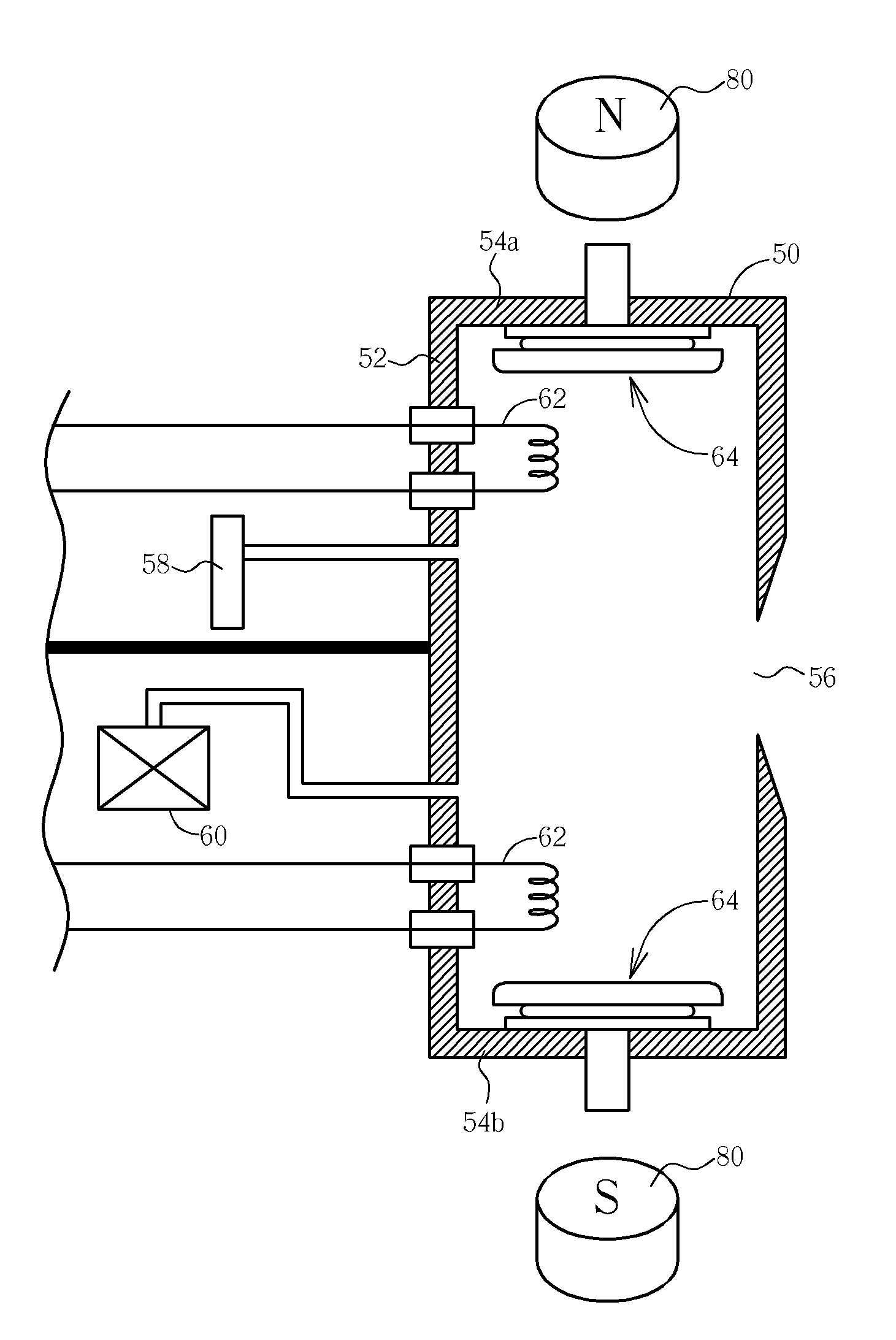
[0018]Please refer to FIG. 3, which is a cross-sectional view of an arc chamber provided by a preferred embodiment of the present invention. As shown in FIG. 3, an arc chamber 50 for an ion implantation system is provided. The arc chamber 50 is of a rectangular form with four elongated side walls 52, a top wall 54a, and a bottom wall 54b. And an exit aperture 56 is positioned at a front side wall 52 allowing an ion beam to be extracted from the arc chamber 50. The arc chamber 50 is made of a conductive material and further comprises a gas inlet port 58 for feeding a gas of desired dopant species such as BF3 or SiF4 into the arc chamber 50 and a vaporizer 60 for vaporizing solid feed materials such as antimony, arsenic, or phosphorus. The arc chamber 50 is also equipped with external magnets 80 respectively positioned at the top wall 54a and the bottom wall 54b.

[0019]As shown in FIG. 3, the arc chamber 50 essentially comprises coiled filaments respectively positioned on two opposing...


PUM


Abstract

An arc chamber for an ion implantation system includes an exit aperture positioned at a wall of the arc chamber, filaments respectively positioned at two opposing sides within the arc chamber, and repeller structures respectively positioned at two opposing walls within the arc chamber between the filaments and the arc chamber. The repeller structure includes a repeller substrate with a screw axis for fitting the repeller structure to the arc chamber, an insulator positioned underneath the repeller substrate providing an electrical isolation between the repeller substrate and the arc chamber, and a conductive spacer covering a portion of the insulator positioned in between the insulator and the arc chamber.

Description

BACKGROUND OF THE INVENTION[0001]1. Field of the Invention[0002]This invention relates to an arc chamber for an ion implantation system, and more particularly, to a repeller of the arc chamber for an ion implantation system.[0003]2. Description of the Prior Art[0004]Ion implantation is a key technology in manufacture of integrated circuits (ICs). In the manufacture of logic and memory ICs, ions are implanted into silicon or GaAs wafers to form transistor junctions, and to dope the well regions of the p-n junctions, etc. A number of dopants or ions have previously been used, such as boron (B), phosphorus (P), arsenic (As), germanium (Ge), and the like. Though those species are of solid elemental form, many are obtainable in gaseous molecular form, such as fluoride compounds that are ionizable in large quantities at significantly elevated temperatures.[0005]Various ion implantation systems are well known, using several types of ion sources. The ion implantation system is a manufacture...

Claims


Application Information

Patent Timeline
Patent Type & Authority Applications(United States)
IPC IPC(8): H01J27/08
CPCH01J27/14H01J37/023H01J2237/038H01J2237/032H01J37/08
Inventor CHEN, JUNG-CHI
Owner UNITED MICROELECTRONICS CORP
Why Eureka
Try Eureka