Hybrid electromechanical power transfer system
- Summary
- Abstract
- Description
- Claims
- Application Information
AI Technical Summary
Benefits of technology
Problems solved by technology
Method used
Image

Examples
Embodiment Construction
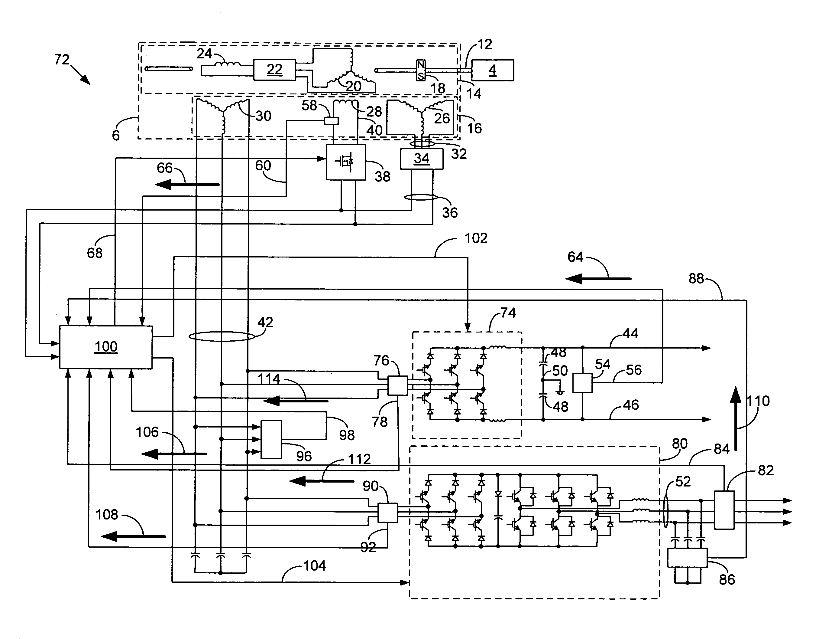
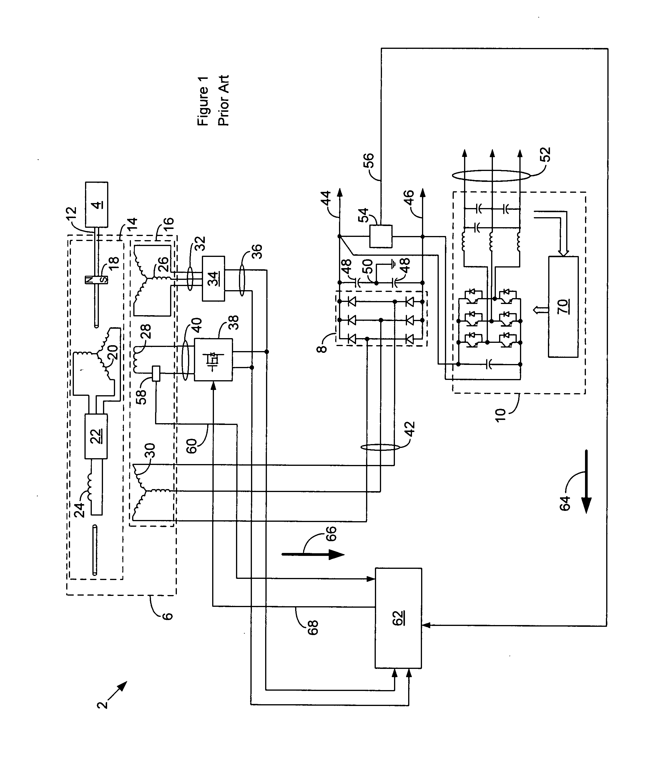
[0016]FIG. 1 is a high-level schematic diagram of an electromechanical power transfer system 2 according to the prior art that utilises a prime mover 4, a dynamoelectric machine 6 of the wound field synchronous type, a rectifier 8 and a PWM inverter 10. The prime mover 4 directly couples to the machine 6 by way of a drive shaft 12. The machine 6 comprises a permanent magnet (PM) rotor assembly 14 and a multiphase stator assembly 16.
[0017]The rotor assembly 14 couples to the prime mover 4 by way of the drive shaft 12. The rotor assembly 14 comprises an auxiliary permanent magnet (PM) rotor 18, a multiphase AC exciter rotor winding 20, a rotating rectifier assembly 22 and a main DC rotor winding 24, all coupled to the drive shaft 12. The multiphase stator assembly 16 comprises an auxiliary multiphase AC stator winding 26 proximate the PM rotor 18, a DC exciter stator winding 28 proximate the exciter rotor winding 20 and a multiphase main stator winding 30 proximate the main rotor wind...
PUM
 Abstract
Description
Claims
Application Information
 - Generate Ideas
- Intellectual Property
- Life Sciences
- Materials
- Tech Scout
- Unparalleled Data Quality
- Higher Quality Content
- 60% Fewer Hallucinations
Browse by: Latest US Patents, China's latest patents, Technical Efficacy Thesaurus, Application Domain, Technology Topic, Popular Technical Reports.
© 2025 PatSnap. All rights reserved.Legal|Privacy policy|Modern Slavery Act Transparency Statement|Sitemap|About US| Contact US: help@patsnap.com