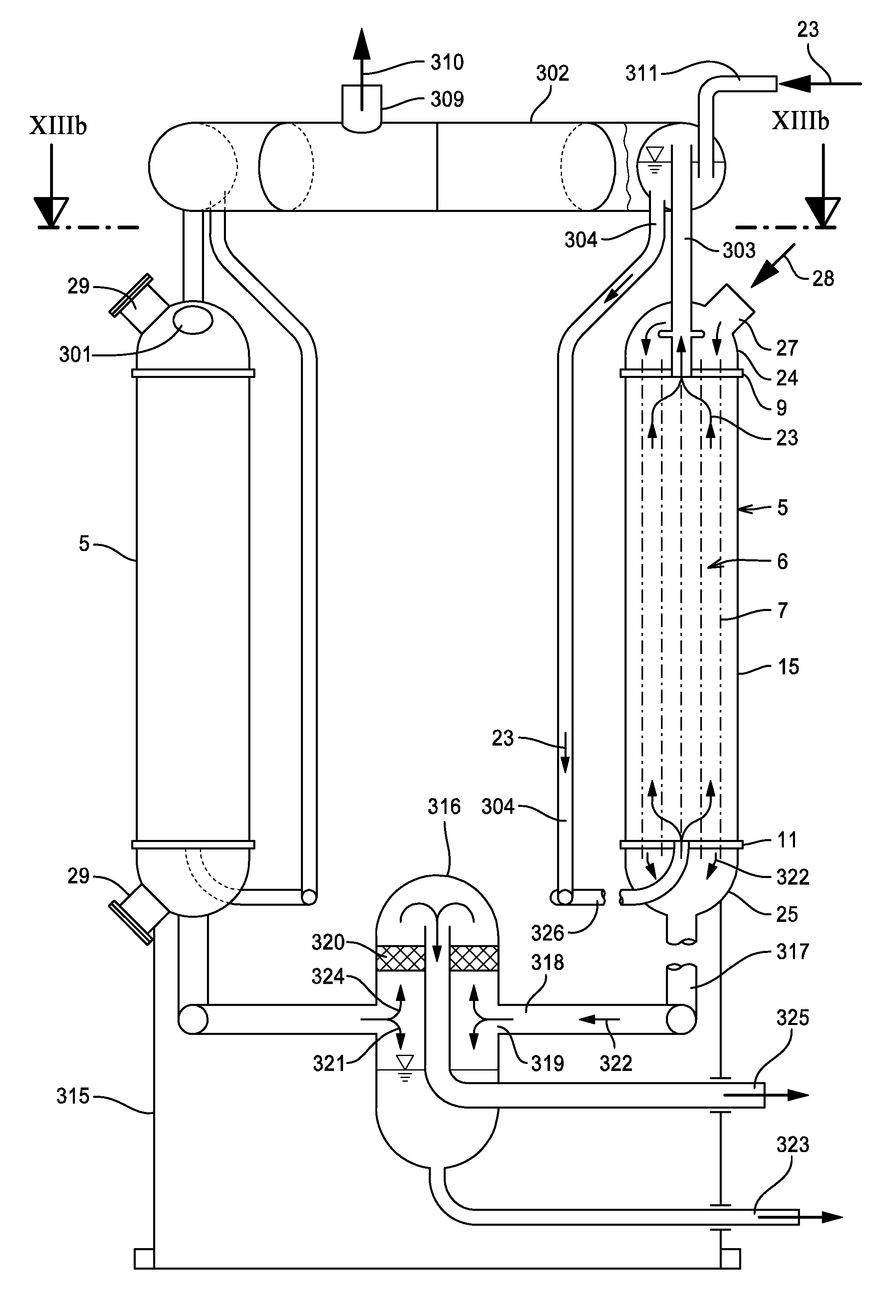
Tube bundle reactors with pressure fluid cooling

a technology of pressure fluid and reactor, which is applied in the field of tube bundle reactors with pressure fluid cooling, can solve the problems of unable or forbidding itself to ship reactors equipped with tubes and having diameters of more than 4 to 5 meters over greater distances, and achieve the effect of great capacity for catalytic gas

Inactive Publication Date: 2009-01-08
MAN ENERGY SOLUTIONS SA
View PDF5 Cites 27 Cited by
  • Summary
  • Abstract
  • Description
  • Claims
  • Application Information

AI Technical Summary

Benefits of technology

[0028]It is, therefore, an object of the present invention to provide a tube bundle reactor unit with pressure fluid cooling and great...

Problems solved by technology

Yet the desired capacity enlargement is subject to limitations imposed by the transportation environment.
True, it has become possible by now to move relatively light apparatus with diameters of some 10 to 11 meters by road but, as a rule, shipment by road or rail of reactors equipped with tubes and having diameters of more than 4 to 5 meters over greater distances is impossible or forbids itself for reasons of cost.
That is so, on the one hand, because of limited vertical and/or horizontal clearances or weight restrictions of bridges and the like and, on the other hand, the lack of suitable hoisting equipment at the place of reloading or the final site of erection.
As regards the first aspect, existing limitations of fabrication at a construction site make it imperative to determine the limits of weights and dimensions of individual reactor elements that will just stay within keeping of the limits imposed by transportation.
It should be noted also that it is very uneconomical and time consuming to equip the reactor with tubing at the construction site only, i.e. to thread the reactor tubes into the tube sheets and seal them to the tube sheets.
In addition, in most cases it will not be possible to accomplish this at the site for lack of proper fabrication conditions and adequate quality assurance.
Besides, the problems of dimensioning still would remain unresolved.
The main obstacle resides in the heat treatment after welding to which component parts with thick walls must be subjected in order to release internal tensions generated in the material by the welding process.
Further disadvantages of the sectoral construction are caused by the fact that the individual sectors dispose of quite a number of planar walls which either must be made unduly thick in view of the pressures prevailing inside the sectors or be reinforced by struts or some other kind of costly support.
Reactor tubes cannot be disposed in the central region of the reactor to utilize this region for reactions.
The whole structure suffers from sealing problems and is susceptible to tension cracks, especially so if operated periodically and under frequently changing operating conditions, respectively.
If the play is too small pinching results and the parts cannot be joined.
Assembling the tube sheet parts at the job site makes little sense.
The diameter of t...

Method used


Image

  • Tube bundle reactors with pressure fluid cooling
  • Tube bundle reactors with pressure fluid cooling
  • Tube bundle reactors with pressure fluid cooling

Examples


Embodiment Construction

[0090]The present invention now will be described more fully hereinafter with reference to the accompanying drawings, in which preferred embodiments of the invention are shown. This invention may, however, be embodied in many different forms and should not be construed as limited to the embodiments set forth herein; rather, these embodiments are provided so that this disclosure will be thorough and complete, and will fully convey the scope of the invention to those skilled in the art. Like numbers refer to like elements throughout.

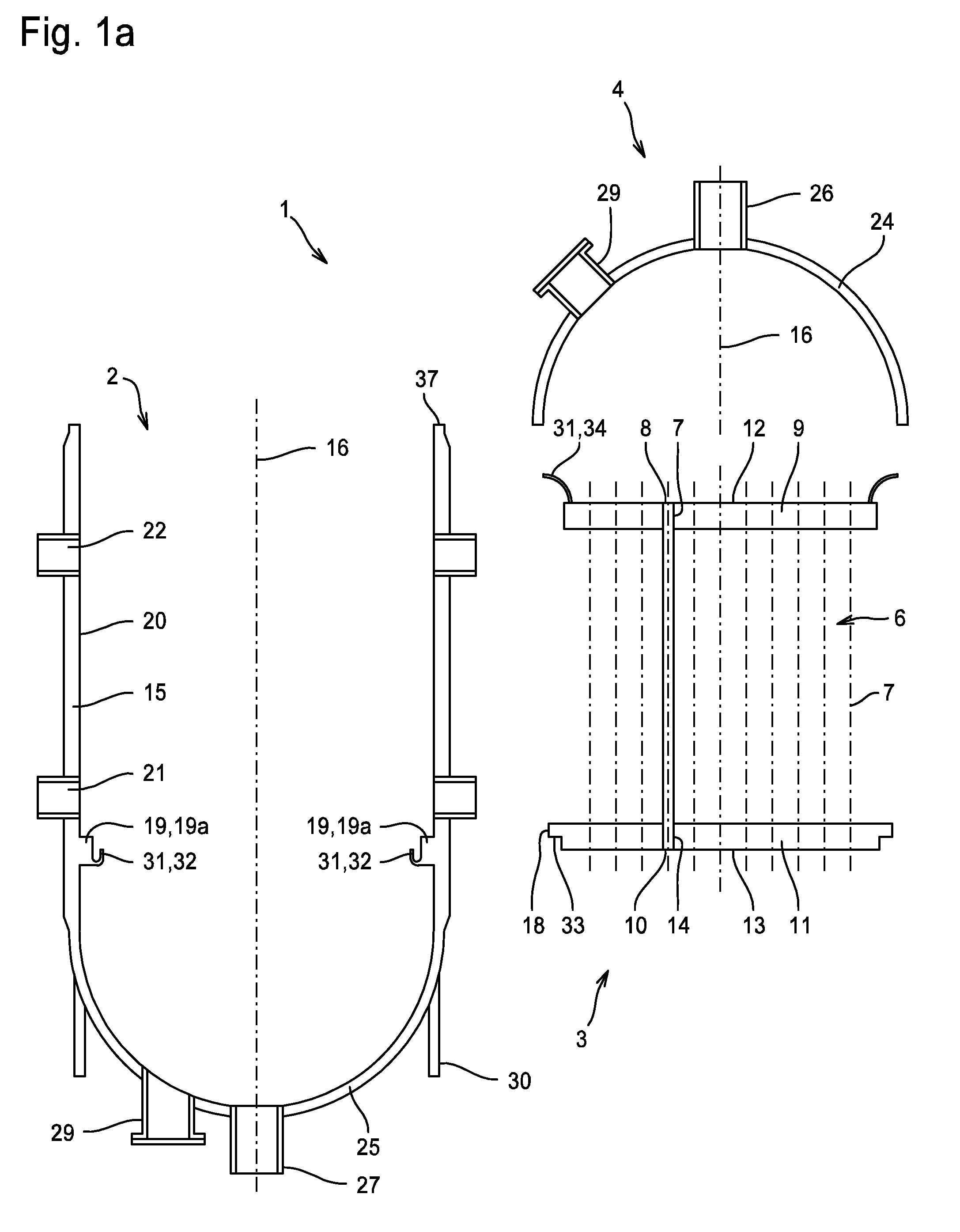
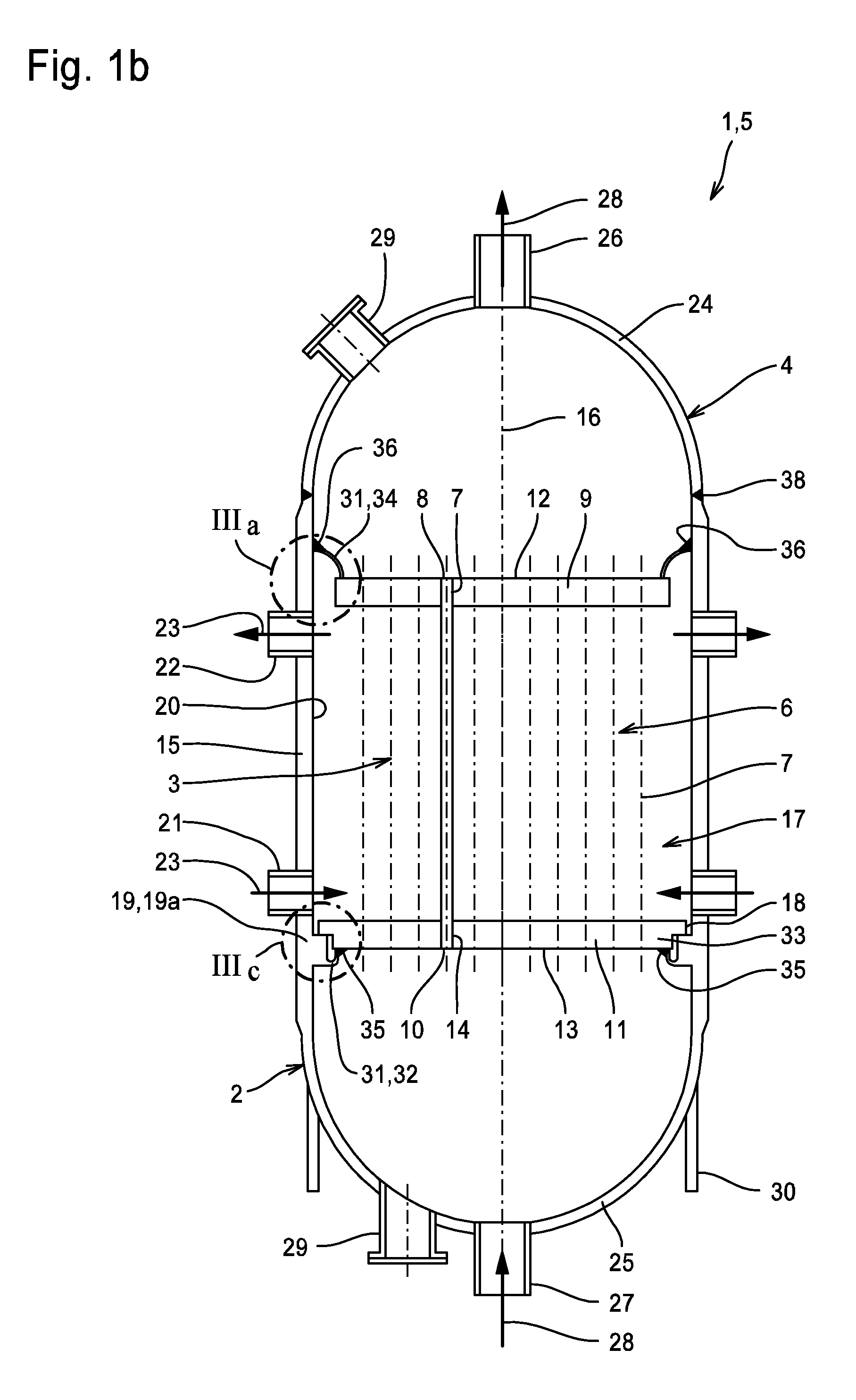
[0091]FIG. 1a shows an embodiment of a set 1 according to the invention of prefabricated tube bundle reactor subassemblies 2, 3, 4 which can be fitted together to form the tube bundle reactor shown in FIG. 1b.

[0092]The tube bundle reactor 5, as fully mounted, may be laid out for catalytic exothermal or endothermal gas and / or liquid reactions to be performed. It comprises a bundle 6 of vertical reactor tubes 7 filled with catalyst. The upper ends 8 of the ...


PUM


Abstract

A set of prefabricated tube bundle reactor subassemblies is proposed which are adapted to be assembled at a construction site to provide a tube bundle reactor for carrying out catalytic gas and/or liquid phase reactions. In accordance with the invention, the reactor shell and the reactor heads, on the one hand, and the tube bundle and the tube sheets, on the other hand, form separate subassemblies, more specifically at least one shell/head subassembly, at least one head subassembly, and at least one tube bundle subassembly. The subassemblies comprise means for vertically supporting the tube bundle subassembly and for pressure tightly connecting the shell/head subassembly to the tube sheets without requiring heat treatment during assembly of the subassemblies. Likewise proposed are a tube bundle reactor for carrying out catalytic gas and/or liquid phase reactions and an arrangement of the kind of tube bundle reactors mentioned.

Description

CROSS-REFERENCE TO RELATED APPLICATIONS[0001]This application claims priority to German Patent Application No. 10 2007 024 934.0, filed May 29, 2007, the contents of which are incorporated herein by reference in its entirety.FIELD OF THE INVENTION[0002]The present invention relates to a set of prefabricated tube bundle reactor subassemblies devised for assembly at a construction site to form a tube bundle reactor for carrying out catalytic gas phase and / or liquid phase reactions. The present invention also relates to a tube bundle reactor and an arrangement of tube bundle reactors.BACKGROUND OF THE INVENTION[0003]Tube bundle reactors comprise a plurality of parallel reactor tubes which are arranged in a tube bundle and into which catalyst material, usually of granular nature is filled. If desired, the reactor tubes also may be filled with inert material or variously combined and arranged catalyst and inert materials. The tube bundle is surrounded by a reactor shell, usually a cylind...

Claims


Application Information

Patent Timeline
IPC IPC(8): B01J19/00
CPCB01J8/008B01J8/067B01J2208/00212B01J2219/0002B01J2219/00038F22B1/1838F28F9/26F28D7/163F28D2021/0064F28F9/00F28F9/013F28F9/0219F28F9/0241F22B21/02
Inventor LEHR, MANFRED
Owner MAN ENERGY SOLUTIONS SA
Why Eureka
Try Eureka