Fuel cell and system

Inactive Publication Date: 2009-01-08
SAMSUNG SDI CO LTD
View PDF9 Cites 7 Cited by
  • Summary
  • Abstract
  • Description
  • Claims
  • Application Information

AI Technical Summary

Benefits of technology

[0009]An aspect of the present invention provides a passive-type fuel cell havin

Problems solved by technology

As the passive-type fuel cell does not have a fuel circulating structure, the passive-type fuel cell has a lower electricity generating efficiency and output.
However, if the fuel concentration is higher than 5M

Method used


Image

  • Fuel cell and system
  • Fuel cell and system
  • Fuel cell and system

Examples


Embodiment Construction

[0022]Reference will now be made in detail to the exemplary embodiments of the present invention, examples of which are illustrated in the accompanying drawings, wherein like reference numerals refer to the like elements throughout. The exemplary embodiments are described below in order to explain aspects of the present invention, by referring to the figures. Herein, when a first element is said to be “disposed” on a second element, the first element can directly contact the second element, or one or more other elements can be located therebetween.

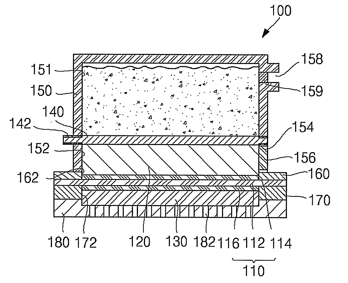
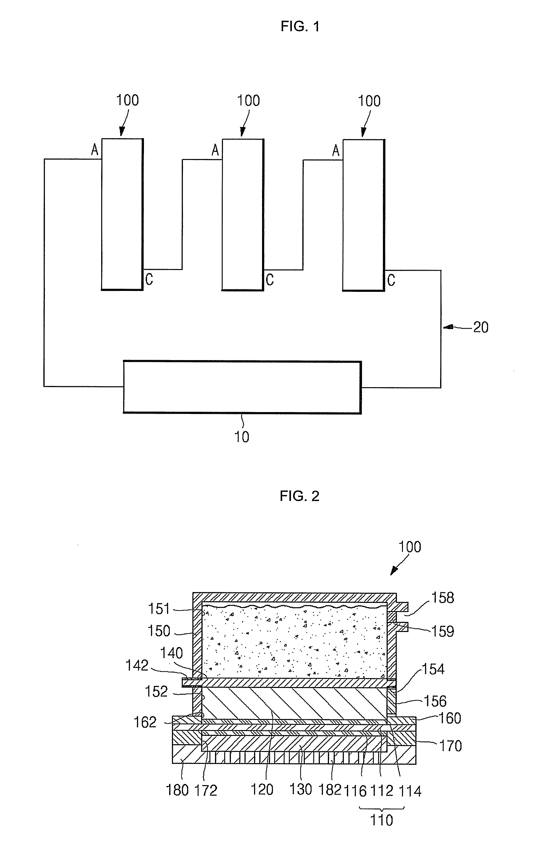
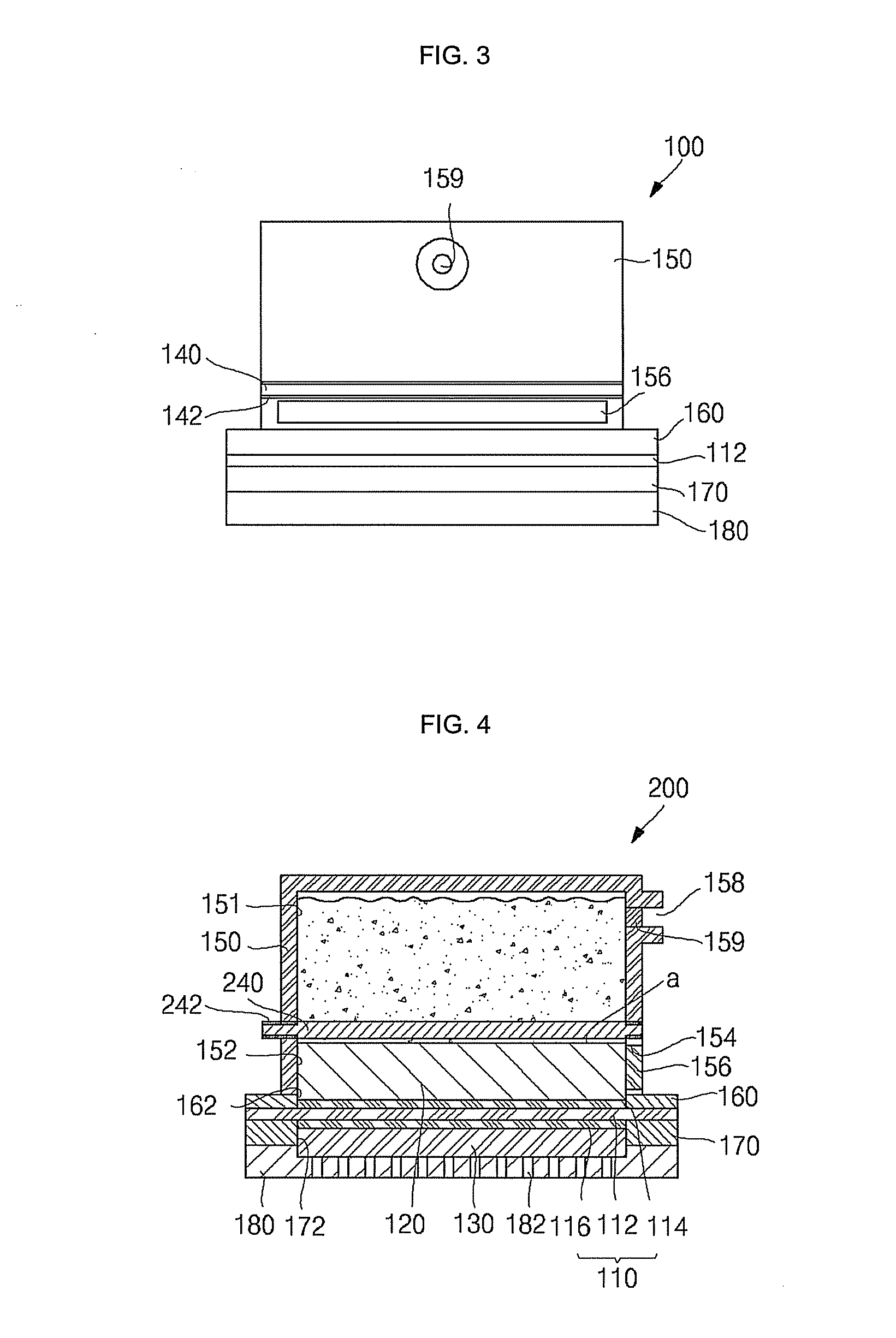
[0023]FIG. 1 is a schematic view illustrating a fuel cell system 20, according to an exemplary embodiment of the present invention, and FIG. 2 is a cross-sectional view illustrating a fuel cell 100, according to an exemplary embodiment of the present invention. FIG. 3 is a plane view illustrating the fuel cell 100, of FIG. 2. Referring to FIGS. 1 to 3, the fuel cell 100 comprises a membrane electrode assembly 110, an anode gas diffusion la...


PUM


Abstract

A the fuel cell that uses a highly concentrated fuel, comprising: a cathode electrode layer; an electrolyte membrane disposed on the cathode layer; an anode electrode layer disposed on the electrolyte membrane; an anode gas diffusion layer disposed on the anode electrode layer; a cathode gas diffusion layer formed thinner than the anode gas diffusion layer on the other surface of the cathode electrode layer; and a porous plate-shaped piezoelectric layer formed on one surface of the anode gas diffusion layer.

Description

CROSS-REFERENCE TO RELATED APPLICATION[0001]This application claims benefit of Korean Application No. 2007-66425, filed Jul. 3, 2007, in the Korean Intellectual Property Office, the disclosure of which is incorporated herein by reference.BACKGROUND OF THE INVENTION[0002]1. Field of the Invention[0003]Aspects of the present invention relate to a fuel cell, and a fuel cell system, both of which having an increased efficiency and output, and using a high concentration fuel.[0004]2. Description of the Related Art[0005]A fuel cell is an electric power generating system that generates electrical energy, by a chemical reaction of hydrogen, contained in hydrocarbon fuel, such as, methanol and ethanol, and oxidants, such as oxygen contained in air supplied thereto. A fuel cell can be a polymer-electrolyte membrane fuel cell (hereafter, referred to as “PEMFC”) or a direct methanol fuel cell (hereafter, referred to as “DMFC”). In general, a PEMFC comprises: a stack (or a main body of the fuel ...

Claims


Application Information

Patent Timeline
IPC IPC(8): H01M8/10
CPCH01M8/04201H01M8/1009Y02E60/50H01M8/241H01M2008/1095H01M8/1011H01M8/02H01M8/04
Inventor SON, INHYUK
Owner SAMSUNG SDI CO LTD
Why Eureka
Try Eureka