Reservoir for a fluid dosing system

a technology of fluid dosing system and reservoir, which is applied in the direction of liquid transferring device, machine/engine, pliable tubular container, etc., can solve the problem of more difficult tampering with the reservoir

Inactive Publication Date: 2009-01-15
DELPHI TECH INC
View PDF8 Cites 25 Cited by
  • Summary
  • Abstract
  • Description
  • Claims
  • Application Information

AI Technical Summary

Benefits of technology

[0033]The reservoir system may also further comprise an air pump to pressurise the air gap with the further fluid. The further fluid may conveniently be supplied from either a tank of fluid or a filling valve.

Problems solved by technology

This advantageously makes tampering with the reservoir more difficult and means that the ECU may be re-set at the reservoir filling location rather than in situ, e.g. on a vehicle.

Method used


Image

  • Reservoir for a fluid dosing system
  • Reservoir for a fluid dosing system
  • Reservoir for a fluid dosing system

Examples


first embodiment

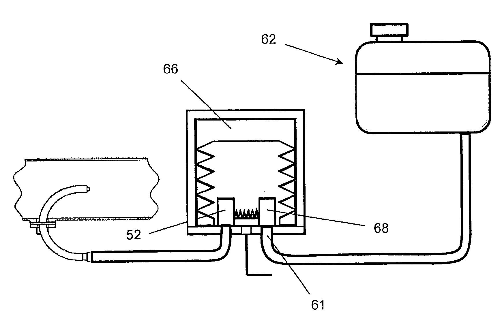
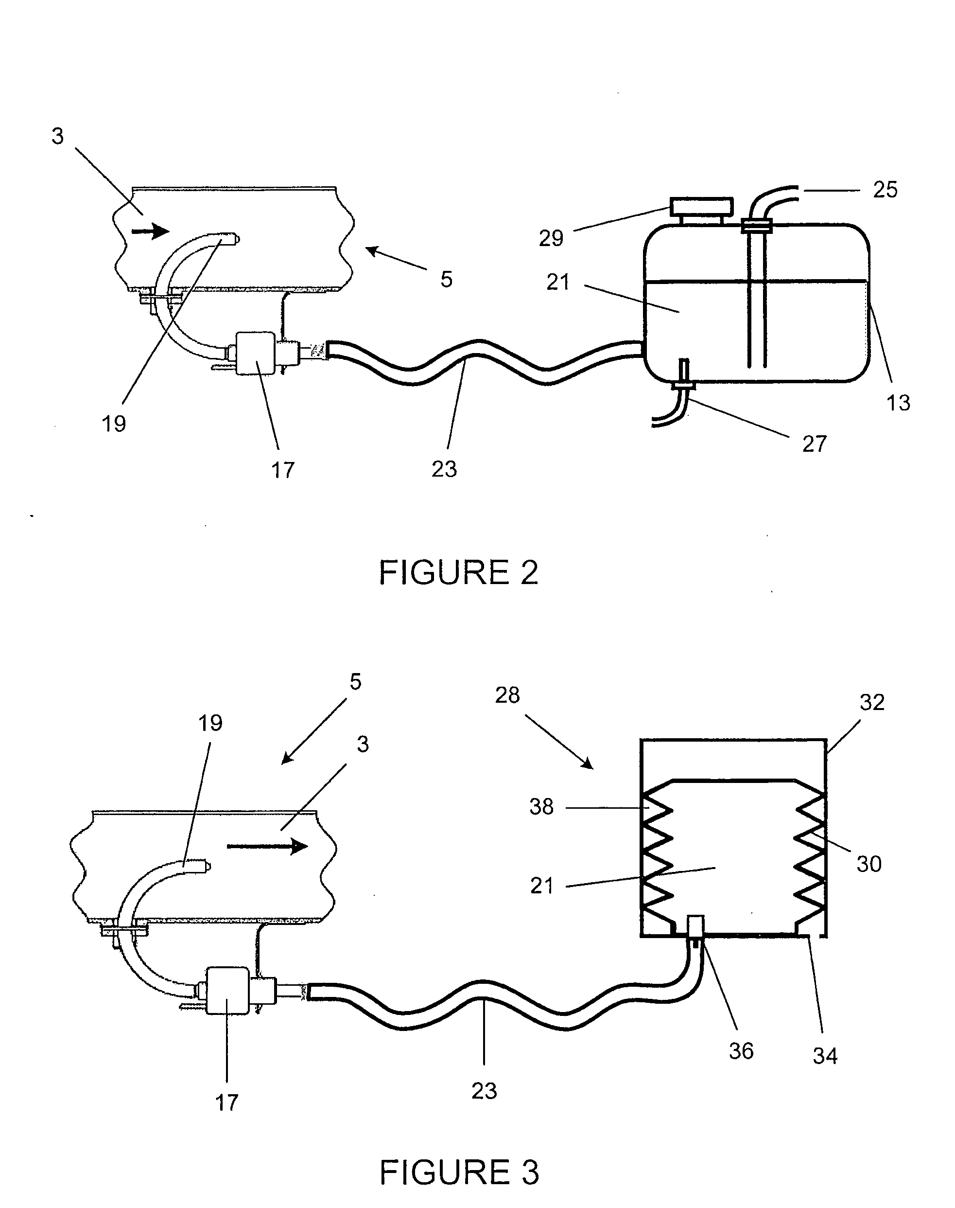
[0053]A reservoir tank, generally indicated as 28, in accordance with the present invention is shown in FIG. 3.

[0054]A reducing agent 21 is contained within a flexible member / container 30 such as a bellows, bag, balloon, collapsible tube, or diaphragm. Suitable materials for the flexible member comprise elastomers, plastics, impermeable fabrics etc. or in the case of a bellows, even thin metal may be used.

[0055]The flexible member is held within a more rigid outer container 32 and the space between the flexible member (the inner container) and the outer container is vented either by a simple hole 34 or via a valve. If a valve is provided, it may be used to control the pressure, or to prevent re-filling of the container except by authorized re-fillers (in order to ensure reagent quality).

[0056]A reagent outlet 36 is provided, which may include a self sealing connection and / or a one way valve to prevent re-filling except by authorized re-fillers.

[0057]If the reagent quality and quanti...

second embodiment

[0059]FIG. 4 shows the present invention in which an ECU 40 and / or a set of other components may be integrated into the reservoir tank. This has additional advantages in that tampering with the container is more difficult and that the ECU may be re-set at the container filling location rather than needing to be done when the container is fitted to the vehicle.

[0060]The embodiment of FIG. 4 also allows integration of functions such as temperature sensing, heating, connections 42 to the dosing unit 17 and / or pipe heaters 44 and connections 46 to the vehicle ECU and / or other sensors to be integrated into one unit, minimizing the number of electrical connections and amount of wiring loom required.

[0061]The provision of a heating means at the bottom of a flexible container means that only the ice at the bottom needs to be melted because the inner container is free to drop down to fill the delivered volume even if the top has solid ice in it. For ease of fitting, all the electrical and fl...

third embodiment

[0062]FIG. 5 shows the present invention in which the outer container 32 is lined with insulation 48. Since the reagent is held within the flexible member the insulation does not need to be reagent proof and may therefore be a cheap and efficient foam or fibre. As well as reducing the likelihood of freezing and reducing the time to thaw, the insulation may also advantageously minimize any noise radiated if lumps of ice knock against the walls of the flexile member 30. The insulation may also provide space for ice within the inner container 30 to expand without applying additional stresses to the outer container 32.


PUM


Abstract

A reservoir for holding a fluid for supply to a fluid dosing device for introducing the fluid into a gas flow, the reservoir comprising: an outer container; an inner container located within the outer container, the inner container being arranged to hold the fluid; an outlet in the outer container, the outlet being in fluid communication with the inner container; wherein the inner container is flexible.

Description

TECHNICAL FIELD[0001]This invention relates to a reservoir for a fluid dosing system. In particular, the invention relates to a reservoir tank for holding a reducing agent for introduction by a fluid dosing device into an exhaust gas flow.BACKGROUND TO THE INVENTION[0002]The emission of nitrogen oxide (NOx) compounds in engine exhausts has long been the focus for health professionals and regulatory agencies worldwide. In many locations, regulations require stringent reductions of NOx levels in new equipments. NOx emissions may be found in a variety of systems such as internal combustion engines, gas turbine exhaust, lean burn engines, industrial boilers, process heaters or other process streams.[0003]In order to reduce NOx emissions, it is known to use a Selective Catalytic Reduction (SCR) device to treat an exhaust flow and to significantly reduce nitrous oxide (NOx) emissions. In an SCR system a reducing agent, for example urea solution, is dosed into the exhaust gas flow upstream...

Claims


Application Information

Patent Timeline
Patent Type & Authority Applications(United States)
IPC IPC(8): F01N3/20B65D83/62B67D5/08B67D7/08
CPCF01N3/2066F01N2610/02F01N2610/10Y02T10/24F01N2610/1413F01N2610/1466F01N2610/1406Y02A50/20Y02T10/12
Inventor COOKE, MICHAEL PETER
Owner DELPHI TECH INC
Why Eureka
Try Eureka