Apparatus and method for a liquid gun

a liquid gun and apparatus technology, applied in lighting and heating apparatus, combustion process, steam boiler components, etc., can solve the problems of uncooled steel surfaces, corrosion, deposition and fouling of furnace walls, etc., and achieve the effect of increasing the flow velocity

Active Publication Date: 2009-01-15
ANDRIZ OY
View PDF9 Cites 2 Cited by
  • Summary
  • Abstract
  • Description
  • Claims
  • Application Information

AI Technical Summary

Benefits of technology

[0027]The flow of the emulsion is accelerated at predetermined intervals for a predefined time for intensifying the cleaning effect. The flow is increased at 1-30 minute (min) intervals, preferably at 5-15 minute intervals, for intensifying the cleaning. The duration of a cleaning cycle is 1-100 seconds (s), preferably 5-20 seconds. During the cleaning of the liquor gun, the total mass flow of the emulsion is increased to 1-50 fold, preferably to 5-20 fold compared to a normal running situation. Preferably the flow of the emulsion is continuous, and it is increased as described above in accordance with the preferred embodiment. The flow of the emulsion can also be intermittent. Thereby, each cycle can also have a stage with an increased flow velocity for intensifying the effect.

Problems solved by technology

In older production plants the dry-solids content of waste liquor may have remained below 65%, which complicates efficient combustion of waste liquor and chemical recovery.
This causes strong corrosion in un-cooled steel surfaces, as well as deposition and fouling on the furnace walls and also e.g. in the liquor guns.
Corrosion is formed also due to accumulation and ignition of unburned waste liquor on the surface of the liquor gun, which causes high temperature and corrosive conditions.
Both fouling of the liquor guns and corrosion deteriorate the liquor spraying process, which has an adverse impact in view of the operation of the furnace.
Typically, one of the major disadvantages of liquor guns is their low resistance.
The low resistance of liquor guns is due to extremely corrosive conditions and high temperature in the furnace and its surroundings, which conditions stress the wall of the gun's metal pipe.
An essential drawback of these devices is limited cleaning and / or cooling effect obtained thereby.
The effect does not extend efficiently to the whole liquor gun, especially not to its outer end on the side of the furnace.
E.g. when using a deflector plate, known liquor guns are devoid of efficient cleaning and cooling of the deflector plate, which are essential factors for that kind of gun, when the aim is good controlling of the combustion in the furnace.

Method used


Image

  • Apparatus and method for a liquid gun
  • Apparatus and method for a liquid gun
  • Apparatus and method for a liquid gun

Examples


Embodiment Construction

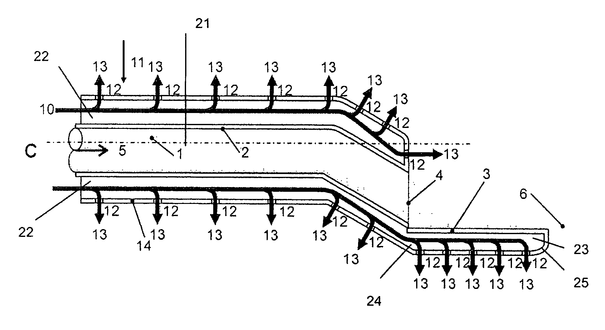
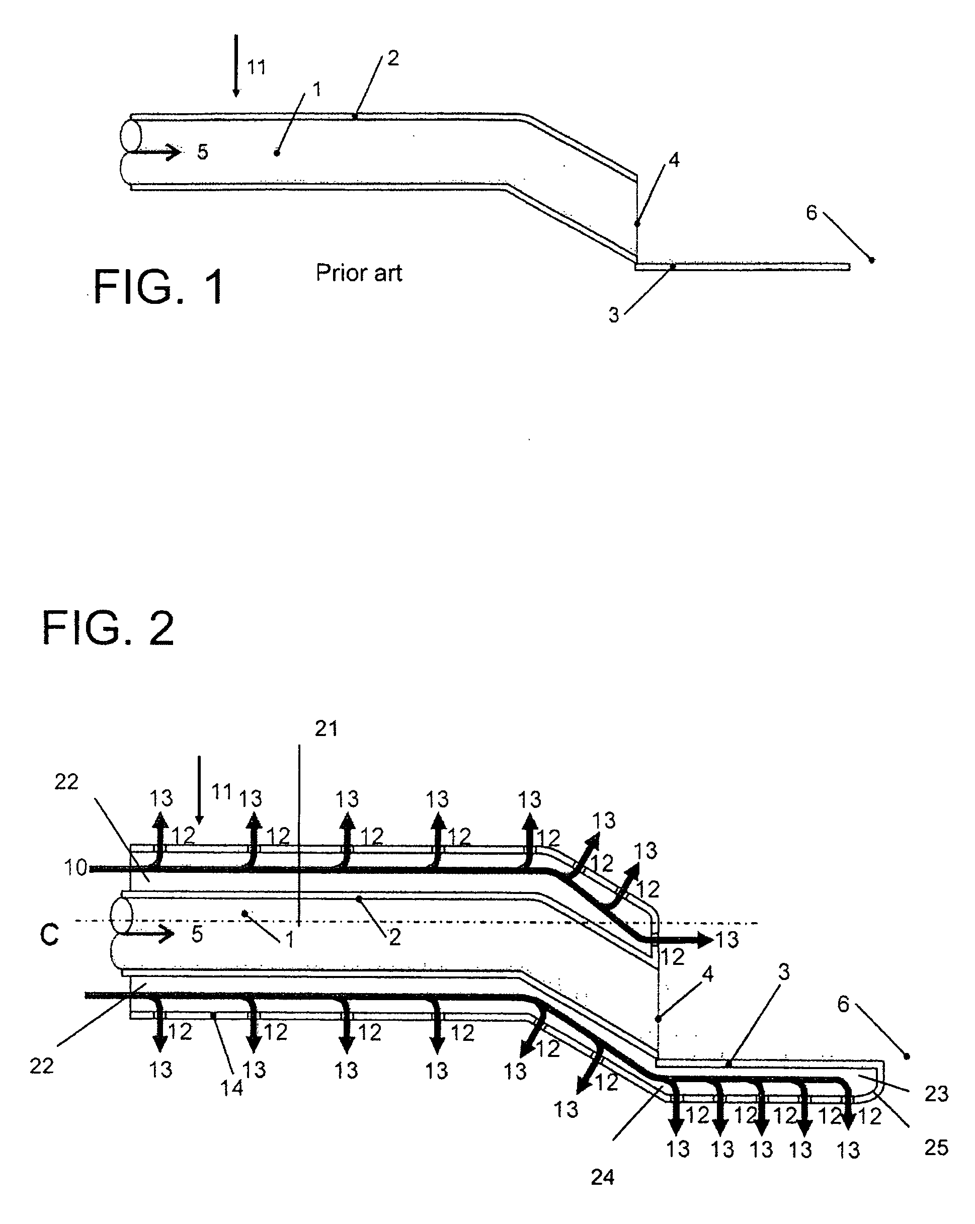
[0034]FIG. 2 illustrates a conventional liquor gun of the type illustrated in FIG. 1, to which cooling and cleaning systems have been added to the liquor gun.

[0035]An outer casing tube 14 is arranged around a liquor spray tube 2. Emulsion 10 formed by water and steam flows into the space surrounding the liquor spray tube 2, to the emulsion space 22. A device (not shown) for producing the emulsion is located prior to the liquor gun. The emulsion is discharged from the emulsion space 22 via pores or holes 12 in form of small jets 13 into the furnace. At the same time, the water in the emulsion is evaporated and binds heat, cooling the outmost surface 14 of the liquor gun. The deflector plate 3 is formed by a double plate structure, the interior 23 of which is in connection with said emulsion space 22 at point 24. Thus, emulsion flows also to the interior 23 of the deflector plate, and the lower surface 25 of the deflector plate is provided with openings 12, wherethrough emulsion is al...


PUM

PropertyMeasurementUnit
diameteraaaaaaaaaa
widthaaaaaaaaaa
lengthaaaaaaaaaa

Abstract

An apparatus for cleaning and cooling a liquor nozzle, the nozzle including at least a liquor tube for feeding liquor and chemicals into a furnace of a recovery boiler. The apparatus includes an outer casing tube, which defines a space whereto conduits are provided for introducing water and steam to generate an emulsion or a conduit for introducing emulsion generated by the water and steam and the surface of which is provided with openings, such as pores or holes, for discharging the emulsion formed by water and steam through the outer casing.

Description

BACKGROUND OF INVENTION[0001]The invention relates to a device for cleaning and cooling a liquor gun, said gun comprising at least a liquor tube for feeding liquor, such as black liquor, into a furnace of a chemical recovery boiler.[0002]In chemical cellulose pulping roughly 35-80% of raw wood material is processed to chemical pulp, so-called “yield”. In chemical pulping the yield is typically 35-55%. The rest of the wood exits the chemical pulp production unit in form of waste liquor that contains, in addition to wood-originating substances, also chemicals used in chemical pulping, which are regenerated for re-use in a so-called recovery unit of the chemical pulp mill. The most common pulp production process is the so-called kraft-process, which generates waste liquid called black liquor. The recovery unit mainly comprises the increase of dry solids in the waste liquor to 65-85%, and even higher, combustion of thus obtained strong waste liquor in the chemical recovery boiler, recov...

Claims


Application Information

Patent Timeline
Patent Type & Authority Applications(United States)
IPC IPC(8): D21C11/12
CPCD21C11/12F23G5/446F23J9/00F23G7/04F23G2900/54402F23G5/48
Inventor TANTTU, MARKKUSAVIHARJU, KARIDU JARDIN, SIRPA
Owner ANDRIZ OY
Why Eureka
Try Eureka