
Layered body and method for manufacturing thin substrate using the layered body

a technology of layered body and thin substrate, which is applied in the direction of film/foil adhesive primer layers, film/foil adhesives, synthetic resin layered products, etc., can solve the problems of inability to separate wafers, method has not yet achieved remarkable improvement over the present level of wafer thickness, etc., to reduce thickness substrate, reduce pressure, and prevent bubbles and dust contamination

Inactive Publication Date: 2009-01-15
3M INNOVATIVE PROPERTIES CO
View PDF67 Cites 55 Cited by
  • Summary
  • Abstract
  • Description
  • Claims
  • Application Information

AI Technical Summary

Benefits of technology

[0005]The present disclosure provides a layered body in which a substrate to be ground is fixed on a support, by means of an acrylate adhesive joining layer comprising a curable acrylate polymer and a curable acrylate adhesion modifying agent, and the joining layer can be easily peeled off from the substrate after grinding and processing steps that require elevated temperatures. The present disclosure further provides a method for manufacturing the layered body and a method for manufacturing a thin substrate using the layered body. In some preferred embodiments, the thin substrate may comprise a semiconductor wafer.
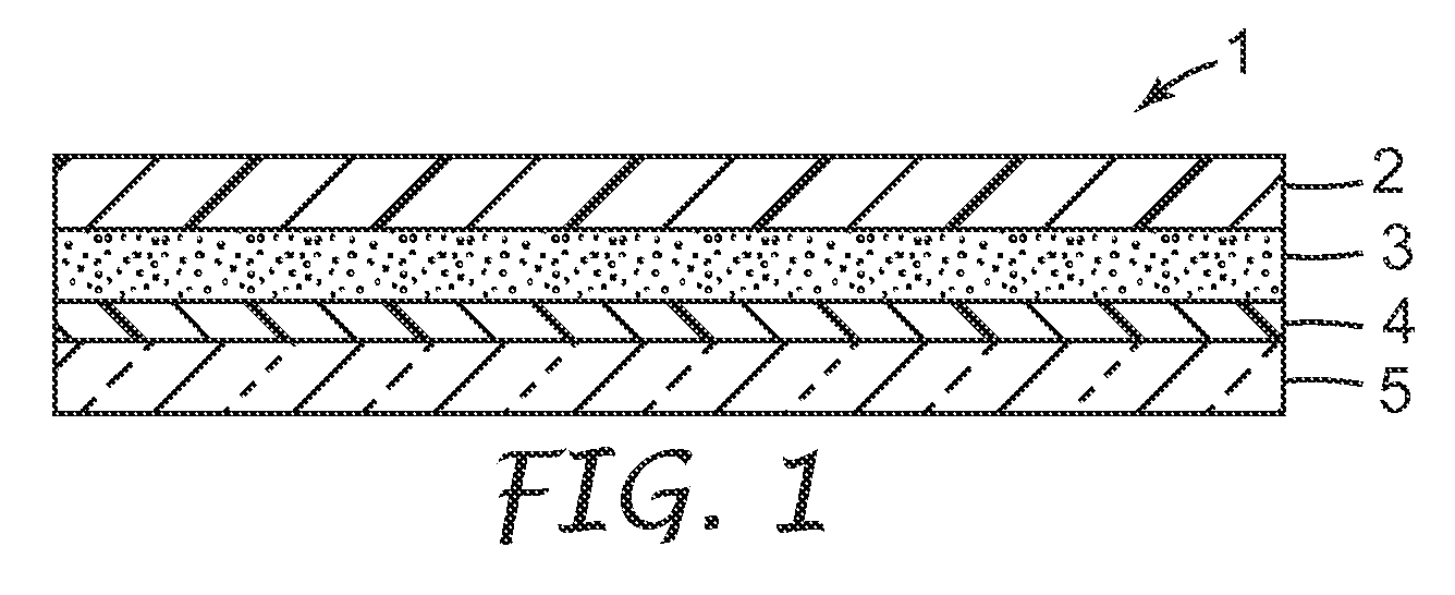
[0006]In one embodiment of the present disclosure, a layered body is provided. The layered body comprises a substrate to be ground; a joining layer comprising a curable acrylate polymer and a curable acrylate adhesion modifying agent in contact with the substrate to be ground; a photothermal conversion layer comprising a light absorbing agent and a heat decomposable resin; and a light transmitting support. After grinding the substrate surface that is opposite the surface that is in contact with the joining layer, the layered body can be irradiated through the light-transmitting support to decompose the photothermal conversion layer and to separate the substrate and the light transmitting support. In this layered body, the substrate that has been ground to a very small thickness can be separated from the support without breaking the substrate.
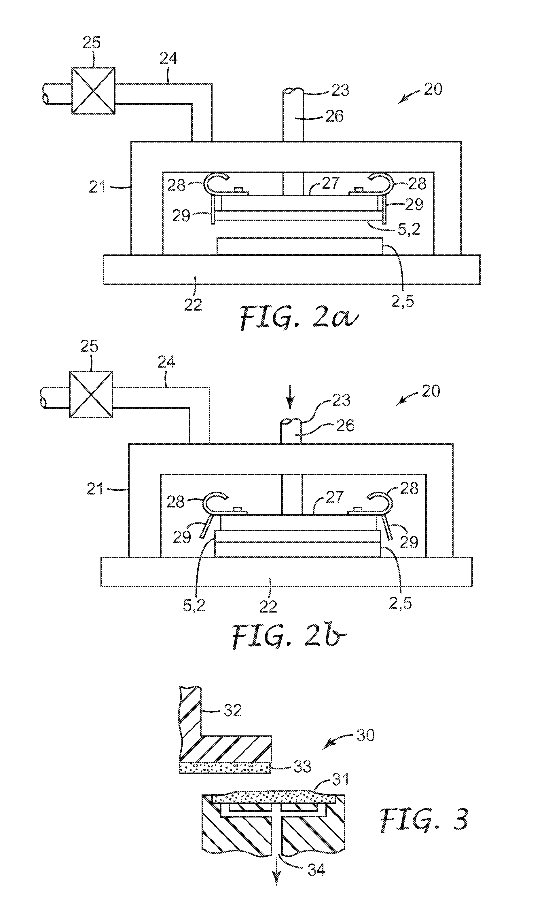
[0008]By joining the substrate to be ground and the light transmitting support through the joining layer under reduced pressure, bubbles and dust contamination are prevented from forming inside the layered body, so that a level surface can be formed and the substrate can maintain the evenness of thickness after grinding.
[0009]In still another embodiment of the present disclosure, a method for manufacturing a reduced thickness substrate is provided. The method comprises the steps of preparing the above-described layered body, grinding the substrate to a desired thickness, irradiating the photothermal conversion layer through the light transmitting support to decompose the photothermal conversion layer and thereby to separate the substrate from the light transmitting support after grinding, and peeling the joining layer from the substrate after grinding. In this method, a substrate can be ground to a desired thickness (for example, 150 μm or less, preferably 50 μm or less, more preferably 25 μm or less) on a support. After grinding and additional processes carried out at elevated temperature, the support is separated from the substrate using exposure to radiation energy, so that the joining layer remaining on the substrate after grinding can be easily peeled from the substrate.

Problems solved by technology

Usually, in conventional techniques of grinding the back side, or surface, of a wafer and conveying it while holding the wafer with only a backgrinding protective tape, thickness reduction can be accomplished in practice only to a thickness of about 150 micrometers (μm) because of problems such as uneven thickness of the ground wafer or warping of the wafer with protective tape after grinding.
However, this method has not yet attained a remarkable improvement over the present level of wafer thickness that may be obtained without encountering the aforementioned problems of unevenness or warping.
According to this method, a wafer can be processed to a lower thickness level as compared with the above-described method, however, the thin wafer cannot be separated from the support without breaking the wafer and therefore, this method may be practically used as a method of thinning a semiconductor wafer.

Method used


Image

  • Layered body and method for manufacturing thin substrate using the layered body
  • Layered body and method for manufacturing thin substrate using the layered body
  • Layered body and method for manufacturing thin substrate using the layered body

Examples


examples

[0089]These examples are for illustrative purposes only and are not meant to be limiting on the scope of the claims. All parts, percentages, ratios, etc. in the examples and the rest of the specification are by weight, unless noted otherwise.

[0090]Table 1 shows the formulation components and trade names that were used in the following examples. The following formulation components do not constitute an exclusive list, but should be interpreted only in light of the comparative examples for which they were used. Those skilled in the art will understand other formulation components may also correspond to a reasonable interpretation of the claims.

Heat Aged Adhesion Testing

[0091]Samples for adhesion testing are prepared by coating an approximately 250 micrometer thick layer of the adhesive formulation between a silicon wafer and a polyester release liner using a standard notch bar coater. The adhesive coating was passed three times under a Fusion “D” bulb set on low power. The conveyer sp...


PUM

PropertyMeasurementUnit
Fractionaaaaaaaaaa
Fractionaaaaaaaaaa
Percent by massaaaaaaaaaa

Abstract

Provided is a layered body including a substrate to be ground and a support, where the substrate may be ground to a very small (thin) thickness and can then be separated from the support without damaging the substrate. One embodiment is a layered body including a substrate to be ground, a joining layer having a curable acrylate polymer and a curable acrylate adhesion modifying agent in contact with the substrate to be ground, a photothermal conversion layer having a light absorbing agent and a heat decomposable resin, and a light transmitting support. After grinding the substrate surface which is opposite that in contact with the joining layer, the layered body is irradiated through the light transmitting layer and the photothermal conversion layer decomposes to separate the substrate and the light transmitting support.

Description

CROSS REFERENCE TO RELATED APPLICATIONS[0001]This application is a continuation-in-part of U.S. Application Ser. No. 11 / 777,328 filed on Jul. 13, 2007, which is hereby incorporated by reference in its entirety.TECHNICAL FIELD[0002]The present disclosure relates to a layered body where a substrate to be ground, such as silicon wafer, fixed on a support can be easily separated from the support even after carrying out processes on the substrate that require elevated temperatures for extended periods, and also relates to a method for manufacturing this layered body and a method for producing a thinned substrate.BACKGROUND[0003]In various fields, reducing the thickness of a substrate often is critical. For example, in the field of quartz devices, reducing the thickness of a quartz wafer is desired so as to increase the oscillation frequency. Particularly, in the semiconductor industry, efforts to further reduce the thickness of a semiconductor wafer are in progress to respond to the goal...

Claims


Application Information

Patent Timeline
IPC IPC(8): B32B27/18B32B37/00B32B7/10H01L21/00H01L51/40
CPCB32B38/18Y10T428/1462B32B2309/68B32B2310/0843B32B2457/14C09J7/0246C09J7/0257C09J2203/326C09J2205/302C09J2433/00C09J2483/00H01L21/67092H01L21/6835H01L21/6836H01L2221/68318H01L2221/68327H01L2221/6834H01L2221/68381H01L2221/68386B32B43/006C09J7/38C09J7/22C09J7/50C09J2301/502
Inventor LARSON, ERIC G.WEBB, RICHARD J.KROPP, MICHAEL A.
Owner 3M INNOVATIVE PROPERTIES CO
Learn More