Subcutanous Blood Vessels Imaging System

a subcutaneous blood vessel and imaging system technology, applied in the field of medical imaging systems, can solve the problems of large number, large number, large field of view, relative slow frame rate, etc., and achieve the effect of clear vein presentation and increased snr (signal-to-noise ratio)

Inactive Publication Date: 2009-01-15
TOOFAN MEHRDAD
View PDF28 Cites 69 Cited by
  • Summary
  • Abstract
  • Description
  • Claims
  • Application Information

AI Technical Summary

Benefits of technology

[0013]A system is disclosed which reveals real time imaging of subcutaneous blood vessels. The subject, whose veins needs to be visualized, is subject to a diffused and broad band infrared light source. Reflected waves from the subject, through a pinhole focusing unit, or alternatively through an infrared focusing lens unit, is focused upon and capt

Problems solved by technology

Although subcutaneous blood vessels could easily be distinguished with the naked eyes for many patients, being able to see these veins for a large number of patients (especially for newborns and small children) constitutes a major problem for physicians for diagnosis purposes, or for those skilled in the medical art who need to perform intravenous administration.
While OCT provides unprecedented resolution, it suffers greatly from small field of view and relative slow frame rates.
In addition, it is expensive to build an OCT.
Finally, the apparatus has a very small filed of view and requires a cumbersome movement of camera around manually to display various portions of skin (See FIG. 1B of the above patent).
Neither of these assertions could be scientifically supported as the visible light hardly can penetrate the skin, and image intensifiers, such as the preferred embodiment of CdS photosensors mentioned in the above patent, do not operate in the infrared range.
The problem with the above arrangement is that light depth penetration into the skin is proportional to the wavelength,

Method used


Image

  • Subcutanous Blood Vessels Imaging System
  • Subcutanous Blood Vessels Imaging System
  • Subcutanous Blood Vessels Imaging System

Examples


Embodiment Construction

is accompanied by referring to the accompanying drawings wherein:

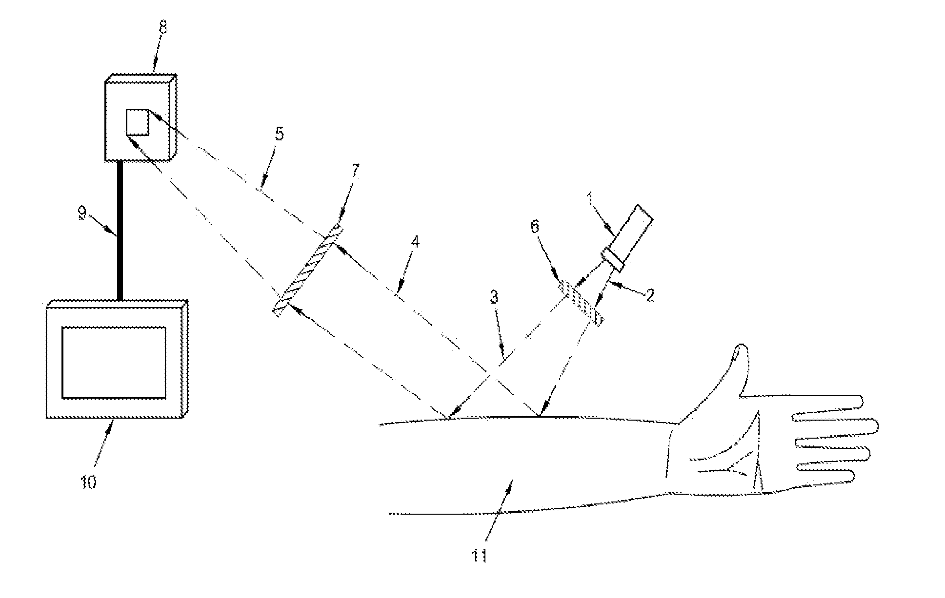
[0019]FIG. 1 illustrates a preferred embodiment of the present invention wherein image of anatomical structures is captured by an infrared Focal Plane Array through a pinhole focusing unit such as a Non-Redundant Array (NRA) aperture, or a Uniformly Redundant Array (URA) aperture, or a Uniformly Distributed Array (UDP) aperture and subsequently being processed and displayed on a display unit.

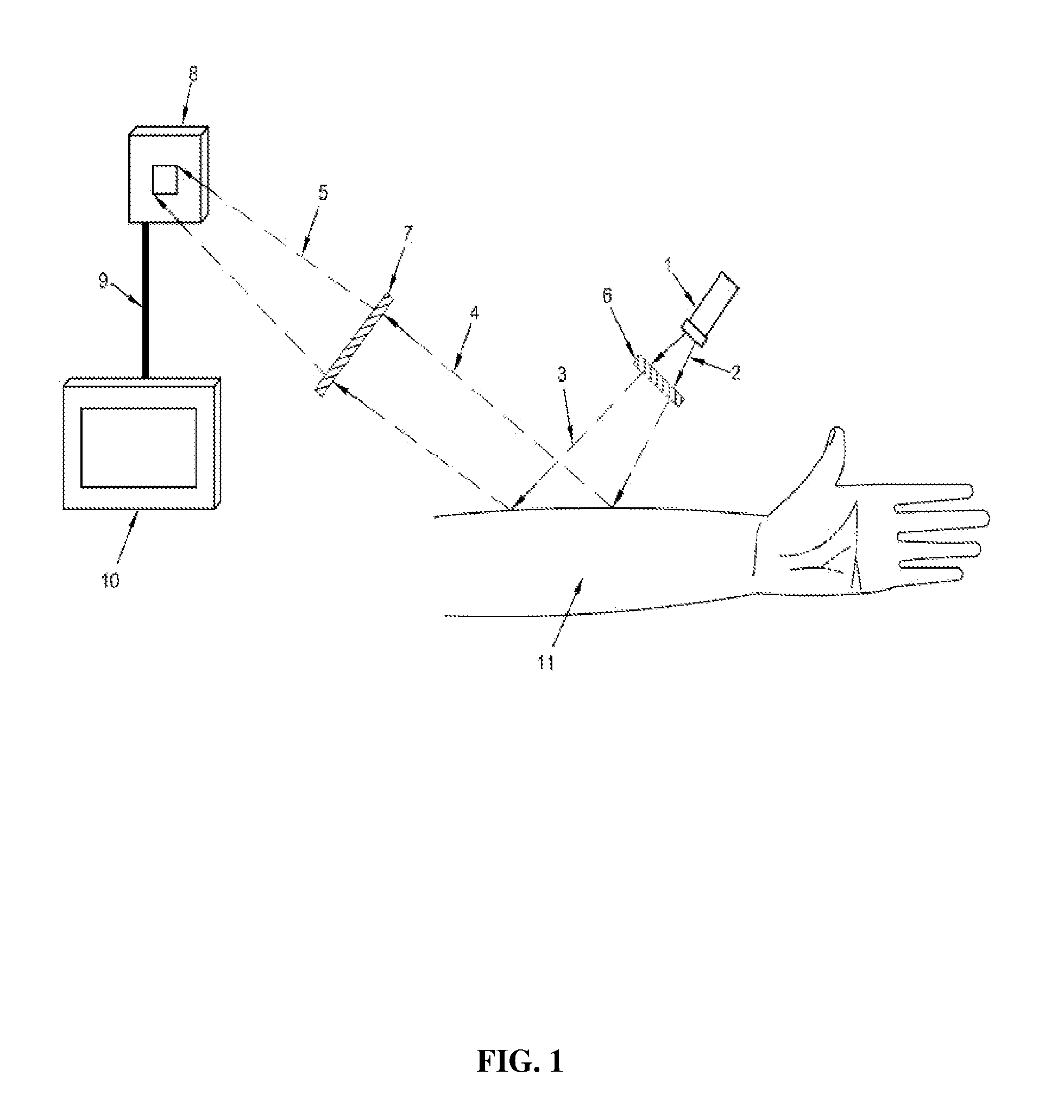
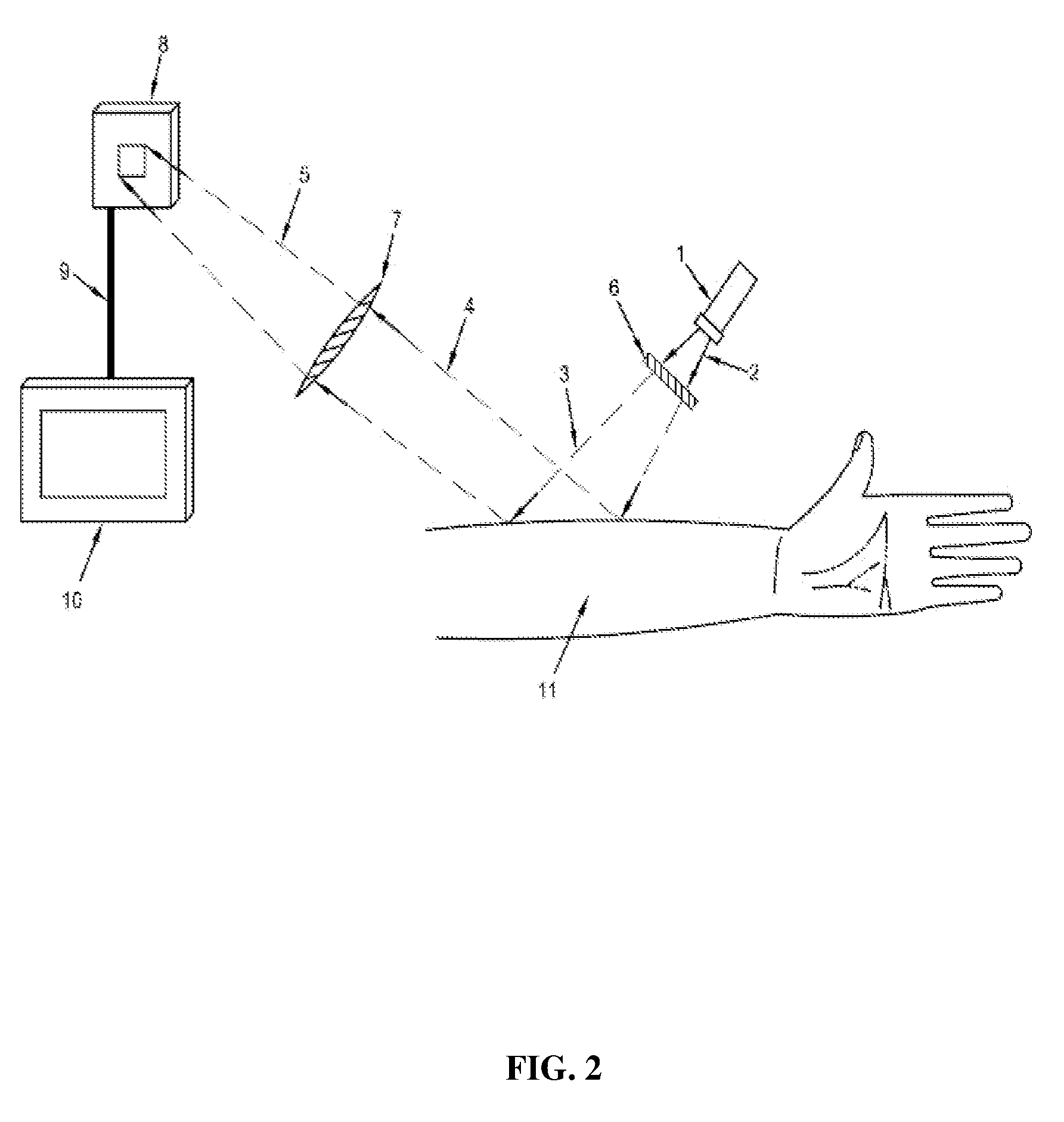
[0020]FIG. 2 illustrates another preferred embodiment of the present invention wherein image of anatomical structures is captured by an infrared Focal Plane Array through an infrared objective lens and subsequently being displayed on a display unit.

[0021]FIG. 3 illustrates the single pinhole selection from a multiple available pinholes to act as the aperture for the present invention.

[0022]FIG. 4 illustrates the possibility of setting the pinhole to any desired radius to act as the aperture for the present invention.

[0023]FIG. 5 il...


PUM


Abstract

A real time imaging system is described which displays subcutaneous veins whereby facilitating diagnosis, inspection and easy intravenous access for administration of drugs. The imaging system comprises an infrared source (1), a pinhole focusing unit (7), an infrared Focal Plane Array (8), and a display unit (10). The infrared source (1) emits infrared light which penetrates and is subsequently scattered differently at different layers and depths of the anatomical structure (11) while substantially being absorbed by the blood vessels. Reflected light (4) from the anatomical structure (11) contains the imaging information of the subcutaneous blood vessels of the anatomical structure (11) which is then focused by said pinhole focusing unit (7) upon said infrared Focal Plane Array (8). The image captured by said infrared Focal Plane Array is then displayed on the display unit (10).

Description

TECHNICAL FIELD[0001]The invention described here relates in general to medical imaging systems and in particular to a system and method to facilitate the viewing of subcutaneous veins. Such visualization would permit a better diagnosis, inspection and easy intravenous access for administration of drugs.BACKGROUND OF THE INVENTION[0002]Having an enhanced visualization of subcutaneous blood vessels is highly desired by those practicing in the medical field. Although subcutaneous blood vessels could easily be distinguished with the naked eyes for many patients, being able to see these veins for a large number of patients (especially for newborns and small children) constitutes a major problem for physicians for diagnosis purposes, or for those skilled in the medical art who need to perform intravenous administration.[0003]Among many imaging techniques introduced to alleviate the problem in prior art, the most commonly referred technique relies on the optical properties of skin and sub...

Claims


Application Information

Patent Timeline
IPC IPC(8): A61B5/103
CPCA61B5/0059A61B5/489A61B5/02007
Inventor TOOFAN, MEHRDAD
Owner TOOFAN MEHRDAD
Why Eureka
Try Eureka