Cooling Apparatus for Fluid

a fluid cooling and fluid technology, applied in the direction of light and heating apparatus, combustion air/fuel air treatment, machines/engines, etc., can solve the problems of deterioration of thermal transfer performance in a certain posture, increased regulation of nox (nitrogen oxides), and heavy burden on vehicle design, so as to reduce fluid resistance, prevent deterioration of thermal transfer performance, and increase the amount of heat transport

Inactive Publication Date: 2009-01-22
KOMATSU LTD
View PDF2 Cites 32 Cited by
  • Summary
  • Abstract
  • Description
  • Claims
  • Application Information

AI Technical Summary

Benefits of technology

[0034]The cooling apparatus of the present invention has at least two passages for a cooling medium. Other ends of the two passages for the cooling medium are communicated with each other, and both of the cooling medium passages have a substantially equal diameter or an equivalent diameter. By setting the diameter or the equivalent diameter of the cooling medium passages to 2 mm to 16 mm, it becomes possible to cause the self-excited vibration. The equivalent diameter herein refers to a diameter in which the fluid resistances of the passages are equal in a case when the cross section of the cooling medium passage that does not have a round shape is represented by the round shape.
[0035]In the present invention, both the steam vaporized after absorbing the heat of the fluid in an endoergic-side heat exchanger and the cooling medium liquefied in an exoergic-side heat exchanger can be passed through the at least two cooling medium passages. This enables a reduction in the fluid resistance. Thus, the condensed fluid is refluxed faster than that only by the gravity, whereby the amount of heat transport can be increased several times.
[0036]In the present invention, since the vibrating force is used as the driving force for circulating the cooling medium, it is unlikely to be affected by the gravity. Thus, deterioration of the thermal transfer performance can be prevented even in the tilted situation.
[0037]In the present invention, a passage for the fluid (exhaust gas) is formed within the endoergic-side heat exchanger. Thus, an endoergic area between the fluid (exhaust gas) and the cooling medium becomes large. This enables the significant increase in the amount of heat input. Therefore, the amount of heat transport becomes large, whereby the large amount of heat from the cooling target having a high temperature such as the EGR gas can be efficiently cooled.

Problems solved by technology

Among others, regulation for NOx (nitrogen oxides) has been increasingly restricted year after year.
As a result, large spaces in the engine room are required for the enlarged those cooling units for the engine, causing a heavy burden of vehicle design.
Additionally, another problem of the above-stated art that employs the gravity for circulating the medium is that the thermal transfer performance significantly deteriorates in a certain posture.
This causes a serious problem especially in a case of application of construction machine.
In the technique as described above that employs the gravity as the circulation force, because of the reduction in the circulation force, the heat radiation becomes insufficient at the time when the construction machine tilts 30 degrees, whereby a temperature of the working medium rises.
Accordingly, pressure of the medium suddenly increases, which may damage the EGR cooler.

Method used


Image

  • Cooling Apparatus for Fluid
  • Cooling Apparatus for Fluid
  • Cooling Apparatus for Fluid

Examples


Embodiment Construction

[0038]Referring now to drawings, an embodiment of a cooling apparatus for a fluid according to the present invention will be described.

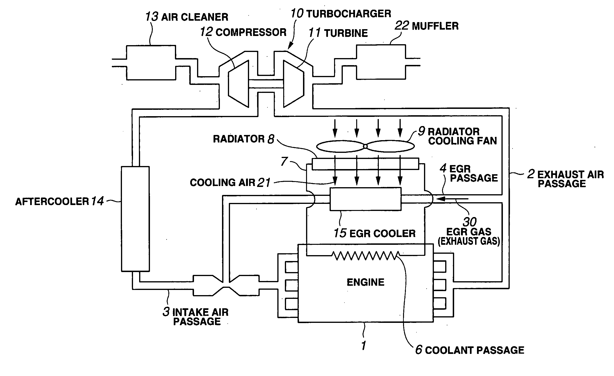
[0039]FIG. 3 shows a layout of an engine room of a construction machine of an embodiment.

[0040]As shown in FIG. 3, an exhaust air passage 2 and an intake air passage 3 in an engine 1 are communicated by way of an EGR passage 4.

[0041]To the EGR passage 4, an EGR cooler 15 is provided. In the EGR passage 4, an EGR gas 30, which is a cooling target of the EGR cooler 15, is introduced from the exhaust air passage 2 and the EGR gas 30 passes. The EGR cooler 15 is a cooling apparatus for cooling the EGR gas 30 to be cooled, and is provided for the purpose of reducing the NOx and so on without degradation in engine power by lowering the temperature of the EGR gas 30 flowing into the intake passage 3 through the EGR passage 4 to increase the charging efficiency of a gas run into a cylinder of the engine 1.

[0042]In the engine 1, a coolant passage 6 for passin...


PUM


Abstract

An apparatus for efficiently cooling the heat of a hot target without enlarging the size of a cooling device or needing either a piping to connect an evaporation portion and a condensation portion or a steam circulation pump. An exoergic-side heat exchanger has a fluid passage for the target fluid, and stores a coolant for cooling the fluid in the fluid passage through heat exchange. An endoergic-side heat exchanger has at least two coolant passages, the one ends of which communicate with the endoergic-side heat exchanger, and the other ends of which communicate with each other through a common coolant passage. A cooling device cools the coolant by exchanging heat with the coolant passing through the exoergic-side heat exchanger. The coolant passage has a diameter or an equivalent diameter within a range of 2 mm to 16 mm, and all the coolant passages have a substantially identical or equivalent diameter.

Description

TECHNICAL FIELD[0001]The present invention relates to an apparatus for cooling a fluid to be cooled such as an exhaust gas and a compressed air.BACKGROUND ART[0002]Recently, restriction on an exhaust gas from a diesel or gasoline engine has become tighter. Among others, regulation for NOx (nitrogen oxides) has been increasingly restricted year after year.[0003]Conventionally, as a method for reducing the NOx, there has been implemented a method of performing recirculation of the exhaust gas emitted from the diesel or gasoline engine and returning to an intake air (Exhaust Gas Recirculation, EGR).[0004]The EGR is a method of returning a part of the inert engine exhaust gas to the intake air of the engine to lower the combustion temperature, thereby reducing the NOx (nitrogen oxides), etc. which are hazardous components in the exhaust gas.[0005]FIG. 1 shows a system for realizing the EGR.[0006]As shown in FIG. 1, an exhaust air passage 2 and an intake air passage 3 in an engine 1 are ...

Claims


Application Information

Patent Timeline
Patent Type & Authority Applications(United States)
IPC IPC(8): F28D1/00F28D15/00F02M31/20
CPCF02M25/0707F02M25/0722F02M25/073F02M25/0731F02M25/0732Y02T10/121F28D1/0435F28D1/0477F28D15/02F28D21/0003F02M25/0737F28D15/0266F02M26/05F02M26/19F02M26/27F02M26/28F02M26/24F02M26/32
Inventor OHSAWA, AKIHIROTSUJIMURA, SHINJICHU, RENCAIHIRAKI, HIKOSABUROU
Owner KOMATSU LTD
Why Eureka
Try Eureka