High frequency coil and magnetic resonance imaging apparatus

a high-frequency coil and magnetic resonance imaging technology, applied in the field of magnetic resonance imaging apparatus and high-frequency, can solve the problems of high manufacturing cost, complicated adjustment, complicated coils and wiring, etc., and achieve the effect of improving the reception sensitivity of the rf coil, simple structure and simple structur

Inactive Publication Date: 2009-01-22
HITACHI LTD
View PDF25 Cites 21 Cited by
  • Summary
  • Abstract
  • Description
  • Claims
  • Application Information

AI Technical Summary

Benefits of technology

[0022]According to the present invention, an RF coil of an MRI apparatus can generate or detect a circular polarized magn...

Problems solved by technology

In this way, in the QD method, the structure of the coils and the wiring are complicated, and a large number of components are required, the adjustment is complicated, and the manufacturing cost is high.
Furthermore, the orthogonality of the coils is degraded, and the transmission efficiency and the reception sensitivity of the coils are degraded due to a phase shift occurring in the distributor, the combiner and the phase shifter and a mechanical strain of the coils.
Since the wavelength of the signal becomes shorter as the frequency increases, In the QD method, the phase shift between the two signals yet ...

Method used


Image

  • High frequency coil and magnetic resonance imaging apparatus
  • High frequency coil and magnetic resonance imaging apparatus
  • High frequency coil and magnetic resonance imaging apparatus

Examples


first embodiment

[0050]In the following, a first embodiment of the present invention will be described.

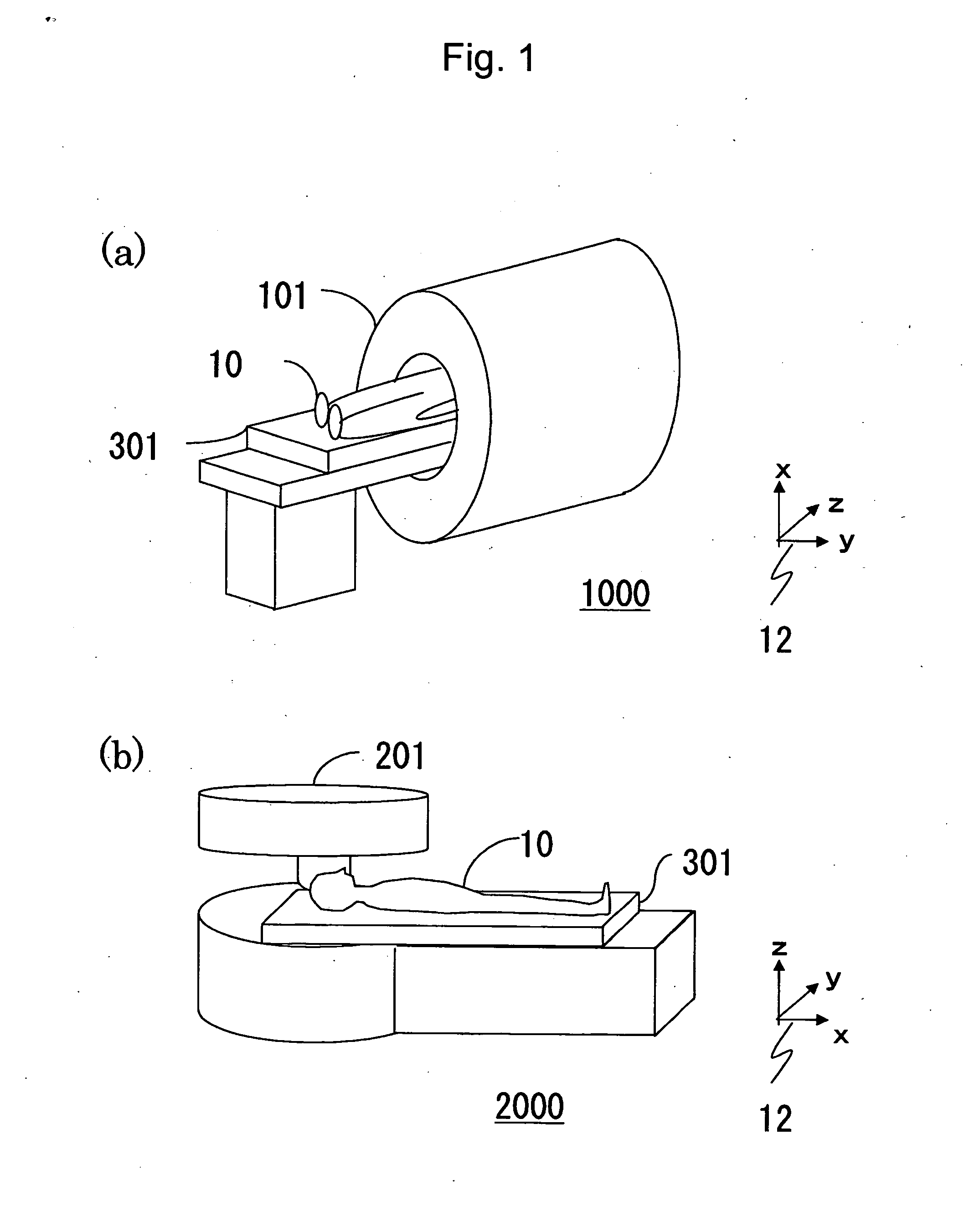
[0051]First, a general configuration of an MRI apparatus according to this embodiment will be described. FIG. 1 includes schematic diagrams showing the MRI apparatus according to this embodiment, in which the direction of the z-axis of a coordinate system 12 is the direction of a static magnetic field. FIG. 1(a) shows an MRI apparatus 1000 having a magnet 101 of horizontal magnetic field type, in which an examinee 10 lying on a table 301 is inserted in an imaging space in a bore of the magnet 101, and an image thereof is taken. FIG. 1(b) shows an MRI apparatus 2000 having magnets 201 of vertical magnetic field type, in which the examinee 10 is inserted in an imaging space between a pair of upper and lower magnets 201, and an image thereof is taken. In this embodiment, either the horizontal magnetic field type or the vertical magnetic field type can be used. In the following, as an example, the hori...

second embodiment

[0105]Now, a second embodiment of the present invention will be described. An MRI apparatus according to this embodiment is essentially the same as that according to the first embodiment. However, unlike the circular polarized RF coil according to the first embodiment composed of two loop coils, a circular polarized RF coil according to this embodiment is composed of a loop coil and a figure-of-eight coil. In the following, differences from the first embodiment will be described. In this embodiment also, the direction of a static magnetic field 100 generated by a magnet 101 of horizontal magnetic field type is the same as the direction of the z-axis of a coordinate system 12.

[0106]FIG. 11 includes diagrams for illustrating a configuration of a circular polarized RF coil 252 according to this embodiment. FIG. 11(a) shows the circular polarized RF coil 252 viewed from a direction perpendicular to the z-axis, and FIG. 11(b) shows the circular polarized RF coil 252 viewed in the directi...

third embodiment

[0119]Now, a third embodiment of the present invention will be described. An MRI apparatus according to this embodiment is essentially the same as that according to the first embodiment. However, unlike the circular polarized RF coil according to the first embodiment composed of two loop coils, a circular polarized RF coil according to this embodiment is composed of two saddle-type coils. In the following, differences from the first embodiment will be described. In this embodiment also, the direction of a static magnetic field 100 generated by a magnet 101 of horizontal magnetic field type is the same as the direction of the z-axis of a coordinate system 12.

[0120]FIG. 13 includes diagrams for illustrating a configuration of a circular polarized RF coil 253 according to this embodiment. FIG. 13(a) shows the circular polarized RF coil 253 viewed from a direction perpendicular to the z-axis, and FIG. 13(b) shows the circular polarized RF coil 253 viewed in the direction of the z-axis (...


PUM


Abstract

To provide an RF coil of an MRI apparatus and improve the irradiation efficiency and the reception sensitivity of a circular polarized magnetic field with a simple structure.
An RF coil has a set of input/output terminals and two loops. The two loops are disposed and capacitors in the loops are adjusted so that the linearly polarized magnetic fields generated and detected by the loops are perpendicular to each other, and the combined magnetic field of the linearly polarized magnetic fields is a circular polarized magnetic field.

Description

CLAIM OF PRIORITY[0001]The present application claims priority from Japanese application JP 2007-187844 filed on Jul. 19, 2007, the content of which is hereby incorporated by reference into this application.BACKGROUND OF THE INVENTION[0002]1. Field of the Invention[0003]The present invention relates to a magnetic resonance imaging (MRI) apparatus and a high frequency (radio frequency) coil for irradiation of an electromagnetic wave or detection of a magnetic resonance signal.[0004]2. Background Art[0005]An MRI apparatus is a medical diagnostic imaging apparatus that causes magnetic resonance of atomic nuclei in an arbitrary cross section of an inspection target and acquires a tomographic image of the cross section, from the magnetic resonance signal produced in the magnetic resonance. If a living body placed in a static magnetic field is irradiated with a high frequency magnetic field from a high frequency coil (RF coil) while applying a gradient magnetic field to the living body, a...

Claims


Application Information

Patent Timeline
IPC IPC(8): G01R33/34
CPCG01R33/34007G01R33/34046G01R33/34076G01R33/3678G01R33/3628G01R33/365G01R33/3657G01R33/3415
Inventor SOUTOME, YOSHIHISAHABARA, HIDETABITO, YOSHITAKA
Owner HITACHI LTD
Why Eureka
Try Eureka