Reflection type display apparatus
- Summary
- Abstract
- Description
- Claims
- Application Information
AI Technical Summary
Benefits of technology
Problems solved by technology
Method used
Image
Examples
example 1
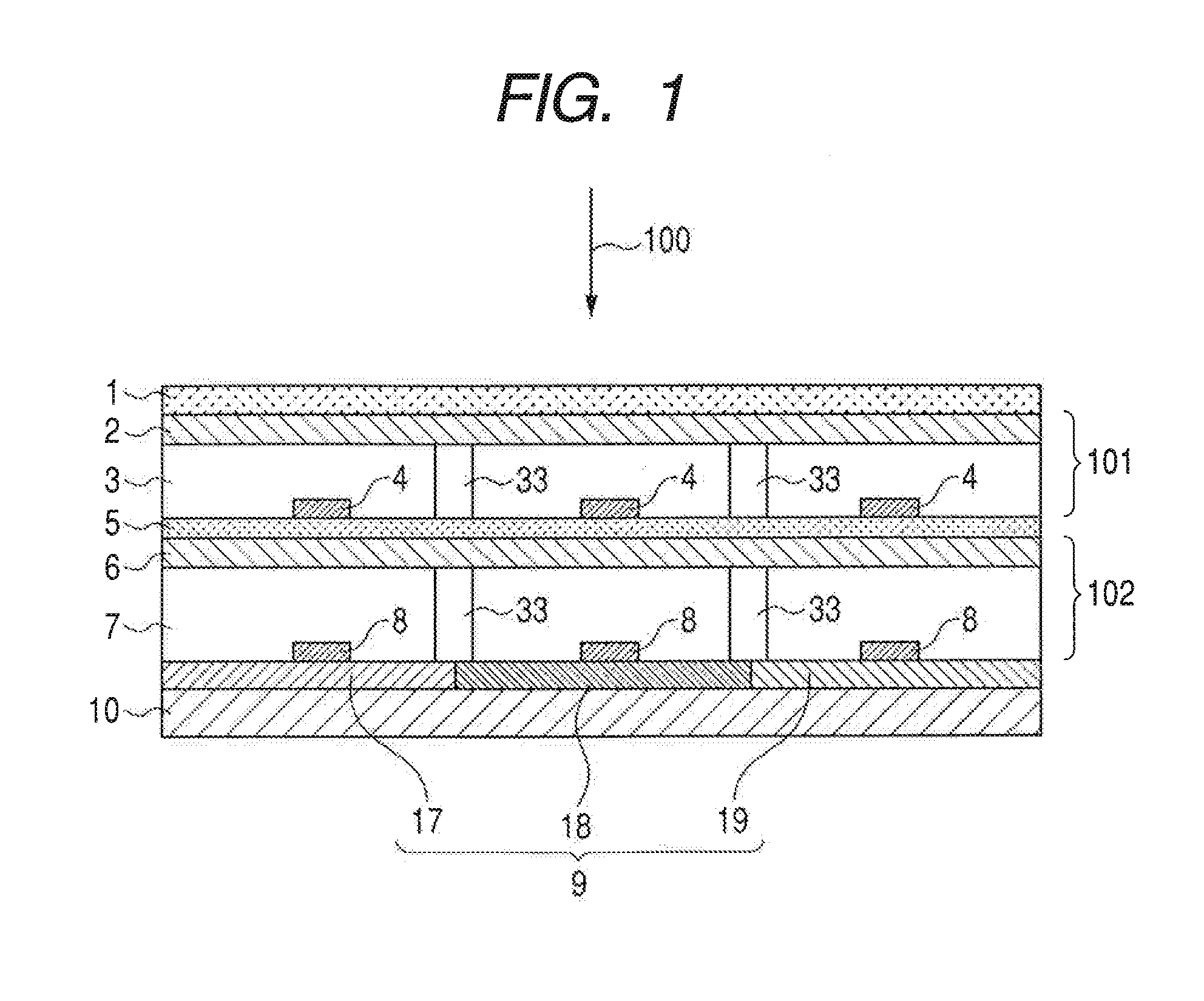
[0056]The specific structure of a reflection type display apparatus according to the present example will be described with reference to FIG. 6. The pixel size of the present apparatus was 0.7 mm×0.7 mm.
[0057](First to Third Supporting Substrates)
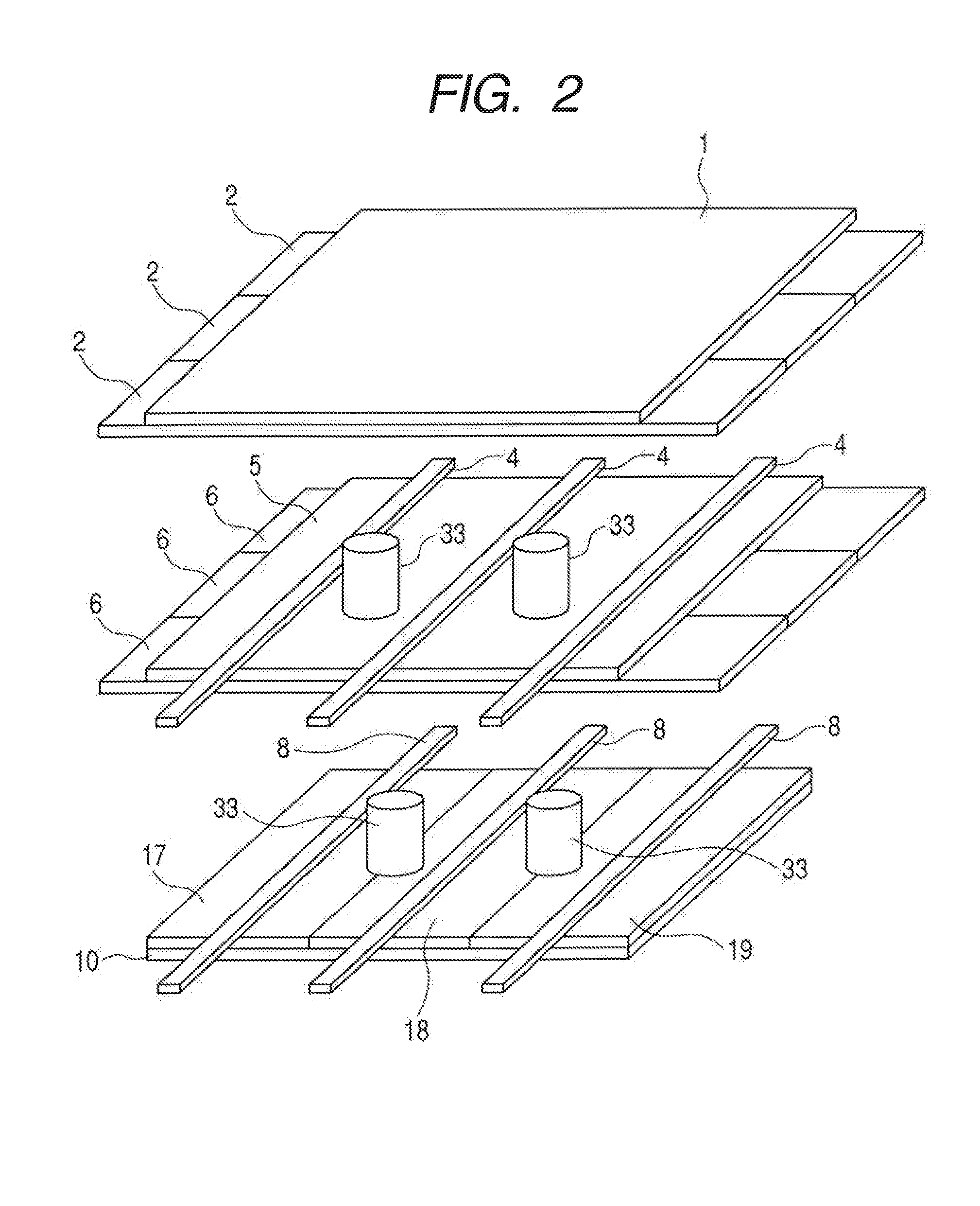
[0058]For the first supporting substrate 1, a glass plate having a thickness of 0.7 mm was used. For the second supporting substrate 5, a glass plate having a thickness of 0.1 mm was used. For the third supporting substrate 10, a silicon wafer was used.
[0059](First Light Modulating Layer)
[0060]For the first electrode 2, an ITO (Indium-Tin-Oxide) film, which is formed by means of sputtering, was used. For the first electrolytic solution 3, a solution containing 200 g / L of nickel sulfate, 5% of ammonia, 20% of zinc chloride, and water. The thickness of the first electrolytic solution 3 was 0.1 mm. For the first counter electrodes 4, platinum wires with a width of 0.1 mm and a thickness of 3 μm was used.
[0061](Second Light Modulating Layer)
[00...
example 2
[0074]In the present example, the reflector in the display apparatus according to Example 1 was provided with components for three colors, i.e., red, green and blue, arranged in a matrix in the Bayer pattern to form a reflection type display apparatus that can provide color display. For the reflector, a laminate of the aforementioned glass plate and colored paper was used. The red, green and blue components arranged in the Bayer pattern, which conform to the pixel size, were printed using a color printer. The pixels were driven by a passive matrix driving method. This display apparatus enabled display of all colors including white and black.
[0075]The color arrangement for the reflector is not limited to the Bayer pattern. The colors are also not limited to the aforementioned ones, and the combination of cyan, magenta and yellow may also be employed. The coloring method is also not limited to a printer. Furthermore, driving can be conducted by means of an active matrix driving method...
example 3
[0076]The display apparatus according to Example 1 displays white in a light reflecting state. As a result, the display exhibits a poor scattering property, which is different from whiteness on paper, and is more like whiteness on a mirror. For displaying white in a manner closer to whiteness on paper, in the present example, as illustrated in FIG. 7, the frontmost surface of the apparatus according to Example 1 was provided with a scattering sheet 22. As a result, the white display had a texture close to that of paper by means of the scattering sheet 22.
[0077]The position where the scattering sheet 22 is arranged is not limited to the frontmost surface, and the scattering sheet 22 may be arranged at any position that is closer to the front surface than the “light reflecting electroplating” formed by electroplating, i.e., any position that is closer to the light incidence side than the second light modulating layer 102 in which a light reflecting state and a light transmitting state...
PUM
 Abstract
Description
Claims
Application Information
 - R&D
- Intellectual Property
- Life Sciences
- Materials
- Tech Scout
- Unparalleled Data Quality
- Higher Quality Content
- 60% Fewer Hallucinations
Browse by: Latest US Patents, China's latest patents, Technical Efficacy Thesaurus, Application Domain, Technology Topic, Popular Technical Reports.
© 2025 PatSnap. All rights reserved.Legal|Privacy policy|Modern Slavery Act Transparency Statement|Sitemap|About US| Contact US: help@patsnap.com


