Unlock instant, AI-driven research and patent intelligence for your innovation.

Low-pressure mercury vapor discharge lamp with amalgam

a mercury vapor discharge and mercury vapor technology, which is applied in the direction of discharge tube luminescnet screens, cathode-ray/electron beam tube circuit elements, vacuum obtaining/maintenance, etc., can solve the problems of amalgam temperature temperature of the lamp to decrease, and the temperature of the lamp to be outside the optimal temperature range, etc. , to achieve the effect of minimizing the number of germicidal lamps, reducing installation costs and maintenance costs

Active Publication Date: 2009-01-29
SIGNIFY HLDG BV
View PDF17 Cites 14 Cited by
  • Summary
  • Abstract
  • Description
  • Claims
  • Application Information

AI Technical Summary

Benefits of technology

[0006]This object is achieved with a lamp system according to the invention, characterized in that the lamp further comprises a heating element arranged at the first end section for heating the amalgam to a temperature within its optimal temperature range, and in that the lamp system further comprises an electronic circuit arranged to generate an electrical discharge current for maintaining the discharge and an electrical heating current for heating the heating element, independently of the electrical discharge current, and a control circuit for generating at least one control signal to activate the electronic circuit to generate the electrical heating current. The amalgam is placed in the end section of the lamp, behind the electrode, in a relatively cool region of the lamp. The amalgam is positioned at the first end section such that in case the lamp operates at maximal input power, the temperature of the amalgam will not exceed the maximum value of its optimal temperature range, so that an optimal mercury-vapor pressure is achieved. The heating element is positioned adjacent to the amalgam. In case the temperature of the amalgam decreases to below its optimal temperature range, for example as a result of dimming the lamp or a decrease in temperature of the surroundings of the lamp, a control circuit activates the electronic circuit of the lamp system to generate an electric current that causes the heating element to heat the amalgam, resulting in an increase of the temperature of the amalgam to within its optimal temperature range. Lamp systems according to the invention operate at a relatively high efficiency over a relatively broad range of operating conditions, such as dimming level, temperature of the surroundings and positioning of the lamp, allowing to minimize the number of (germicidal) lamps required for a specific application, and thus reducing installation costs as well as maintenance costs.
[0010]Another preferred embodiment of the lamp system according to the invention is characterized in that the first electrode is further arranged to operate as the heating element. By using the first electrode for heating the amalgam, a relatively simple construction for controlling the amalgam temperature is provided.
[0016]According to the invention, a water treatment system or an air treatment system comprises at least one lamp system according to the invention. Lamp systems according to the invention operate at a relatively high efficiency over a relatively wide temperature range of the lamp and a wide range of operating conditions, allowing to minimize the number of germicidal lamps required for a specific water treatment system or air treatment system and thus reducing installation costs as well as maintenance costs. As the amalgam is positioned within a relatively cool region of the discharge space, it can be prevented that the amalgam melts during operation of the germicidal lamps and consequently moves out of position when the germicidal lamp is used in a vertical position.

Problems solved by technology

However, under certain conditions the temperature may change in such a way that the temperature of the amalgam is outside its optimal temperature range.
Furthermore, when using germicidal lamps for waste water treatment, for disinfection of drinking water, or for air treatment, a decrease in the temperature of the water or air causes the temperature of the lamp to decrease.

Method used


Image

  • Low-pressure mercury vapor discharge lamp with amalgam
  • Low-pressure mercury vapor discharge lamp with amalgam
  • Low-pressure mercury vapor discharge lamp with amalgam

Examples


second embodiment

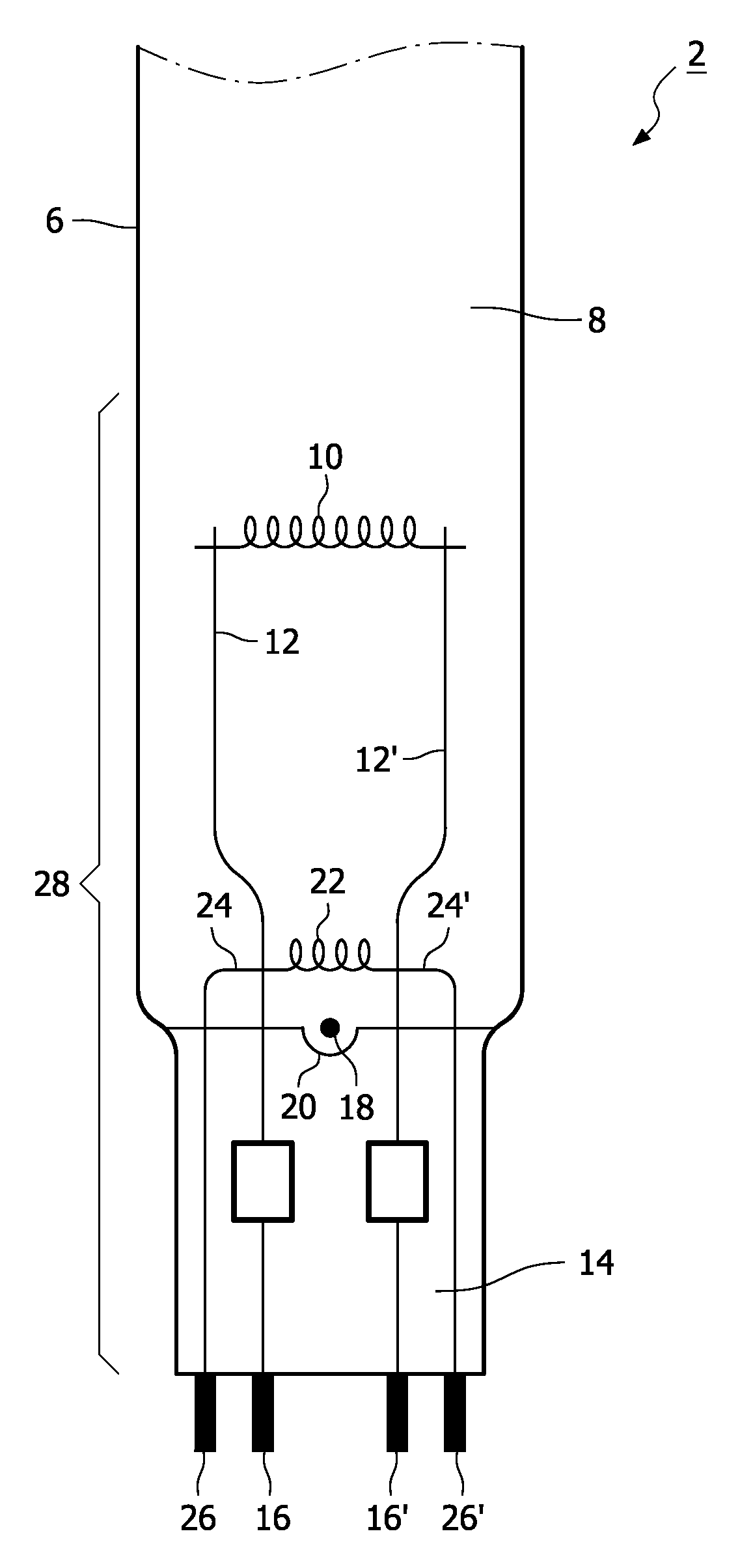
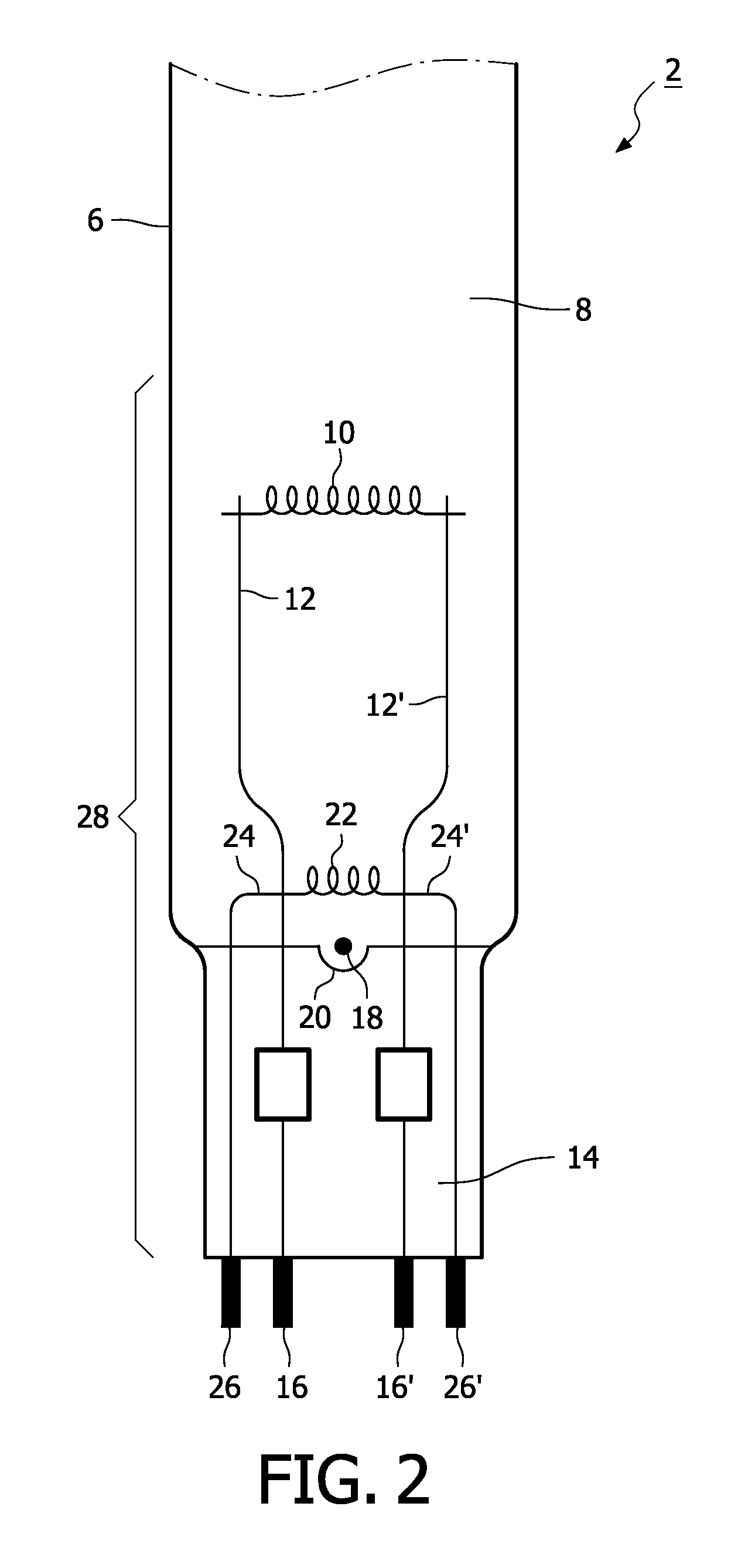
[0029]FIGS. 2 and 3 are schematic drawings of a first and a second embodiment, respectively, of a low-pressure mercury vapor discharge (germicidal) lamp for the lamp system as shown in FIG. 1. The lamp 2 has a gas discharge vessel 6 that encloses, in a gastight manner, a discharge space 8 containing a filling of mercury and an inert gas, for example argon. For clarity reasons, only a part of the lamp 2 is shown. The lamp 2 has two electrodes, of which only electrode 10, 30 is shown. Electrode 10, 30 is positioned in a first end section 28 of the germicidal lamp 2, and a second electrode is positioned in a second end section of the lamp, for maintaining a discharge in the discharge space 8. Alternatively, the electrodes are external electrodes. The electrode 10, 30 is a winding of tungsten covered with an electron-emitting substance, for example a mixture of barium oxide, calcium oxide and strontium oxide. Current-supply conductors 12, 12′ are coupled to the electrode 10, 30 and pass...

fifth embodiment

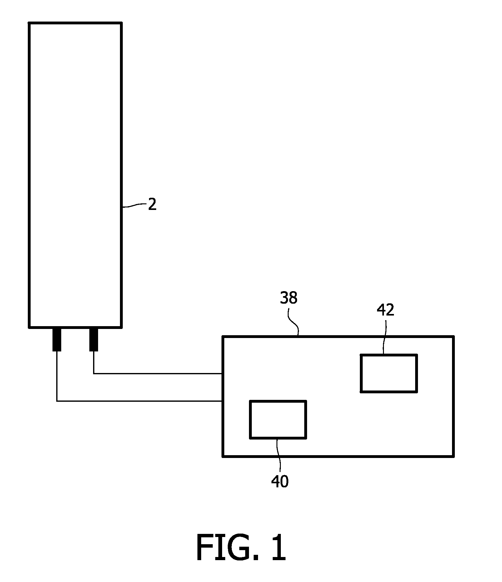
[0030]FIGS. 4, 5 and 6 are schematic drawings of a third, fourth and fifth embodiment, respectively, of a low-pressure mercury vapor discharge (germicidal) lamp for a lamp system according to FIG. 1. Referring to FIGS. 4, 5 and 6, for clarity reasons, only a part of the lamp 2 is shown. The lamp 2 has a gas discharge vessel 6 that encloses a discharge space 8 containing a filling of mercury and an inert gas mixture, for example argon. The lamp 2 has two electrodes, of which only electrode 30 is shown. Electrode 30 is positioned in a first end section 28 of the lamp 2, and a second electrode is positioned in a second end section of the lamp, for maintaining a discharge in the discharge space 8. Alternatively, the electrodes are external electrodes. Current-supply conductors 12, 12′ are coupled to the electrode 30 and pass through the sealed end 14 of the lamp to the exterior. The current-supply conductors 12, 12′ are connected to contact pins 16, 16′. The lamp ballast 38 is arranged ...


PUM


Abstract

The invention relates to a lamp system comprising a low-pressure mercury vapor discharge lamp having a discharge vessel (6) enclosing a discharge space (8), with two electrodes (10, 30) positioned in the discharge vessel and an amalgam (18) arranged at a first end section (28) outside the discharge path between the first electrode and the second electrode. A ballast generates an electrical discharge current independently of an electrical heating current. A heating element (22) is positioned in the first end section for heating the amalgam using the electrical heating current. The temperature of the amalgam can be kept within its optimal temperature range for a relatively broad range of operating conditions.

Description

TECHNICAL FIELD[0001]The invention relates to a lamp system comprising a low-pressure mercury vapor discharge lamp, the lamp comprising at least one discharge vessel enclosing, in a gastight manner, a discharge space provided with a filling of mercury and a rare gas, the discharge vessel having a first end section and a second end section, a first electrode arranged at the first end section and a second electrode arranged at the second end section for maintaining a discharge along a discharge path between the first electrode and the second electrode, and an amalgam for regulating the mercury vapor pressure in the discharge vessel and having an optimal temperature range, arranged at the first end section outside the discharge path. The invention further relates to a water treatment system or an air treatment system comprising said lamp system. The invention also relates to a low-pressure mercury vapor discharge lamp for said lamp system. The invention also further relates to the use ...

Claims


Application Information

Patent Timeline
IPC IPC(8): H01J61/52
CPCH01J61/28H01J61/70H01J61/523H01J61/72
Inventor VAN DEN BROEK, ANTONIUS CORNELISELEN, JOHNKLOEK, FRANKLENAERTS, KOENESCH, HELEENGEBOERS, JAAK
Owner SIGNIFY HLDG BV