Ceramic drill bit for high-speed drilling of composites

a ceramic drill bit and composite technology, applied in the direction of twist drills, manufacturing tools, wood boring tools, etc., can solve the problems of accelerated degradation of ceramic drill bits, increased drilling depth, and distortion of parts, so as to prevent delamination

Active Publication Date: 2009-01-29
SN DETUDE & DE CONSTR DE MOTEURS DAVIATION S N E C M A
View PDF22 Cites 22 Cited by
  • Summary
  • Abstract
  • Description
  • Claims
  • Application Information

AI Technical Summary

Benefits of technology

[0012]Thus, the flank and rake faces of the drill bit head are extended, radially toward the outside, by a first curved bevel forming a flank surface and by a second bevel forming a rake surface, respectively. The inward curvature of the first and second bevels prevents delamination of the composite drilled by the drill bit.

Problems solved by technology

However, the possible constraints on a drill bit (drilling depth, removal of the chips, intensity and direction of the cutting forces) during a drilling operation are greater than those that may be applied on a milling cutter during a milling cutting operation.
These constraints make it more difficult to use ceramic drill bits for carrying out drilling operations at very high speed in very hard materials such as metal superalloys.
This is because the cutting forces, exerted by these drill bits on the parts to be drilled and the frictional forces between the radially external surfaces of the drill bits and the internal cylindrical surfaces of the drilled holes, induce thermal stresses, both in the drill bits and in the parts to be drilled, and an abrasion phenomenon which together result in accelerated degradation of the drill bits and distortion of the parts.
Furthermore, as the depth of the drillholes increases, the applied torsional forces on the drill bits become more and more significant, not only because the external surface of the drill bit rubbing against the internal cylindrical surface of the drillhole increases, but also because, for high drilling speeds, the drill bit must be capable of removing a large quantity of chips effectively, which may cause jamming in the drill bit, thus increasing the applied torsional forces on the drill bit and the risks of the latter breaking.
This additional constraint contributes to premature wear of the tool and to an increase in the risk of it breaking.
Another constraint on the machining, and in particular the drilling, of composites is that the operation must be carried out while preserving the integrity of the drilled material.
Thus, although tools, especially drill bits, the active part of which is made of a ceramic, capable of machining very hard materials at high speed, such as metal superalloys, are commercially available, the known drill bits of the prior art do not allow suitable high-speed machining of composites, particularly carbon-fiber composites having an epoxy resin matrix.
For example, the drill bit described in patent FR 2 861 001 is indeed suitable for high-speed drilling of very hard metallic materials, but it is not suitable for composites, causing in this case delamination of the material to be machined.

Method used


Image

  • Ceramic drill bit for high-speed drilling of composites
  • Ceramic drill bit for high-speed drilling of composites
  • Ceramic drill bit for high-speed drilling of composites

Examples


Embodiment Construction

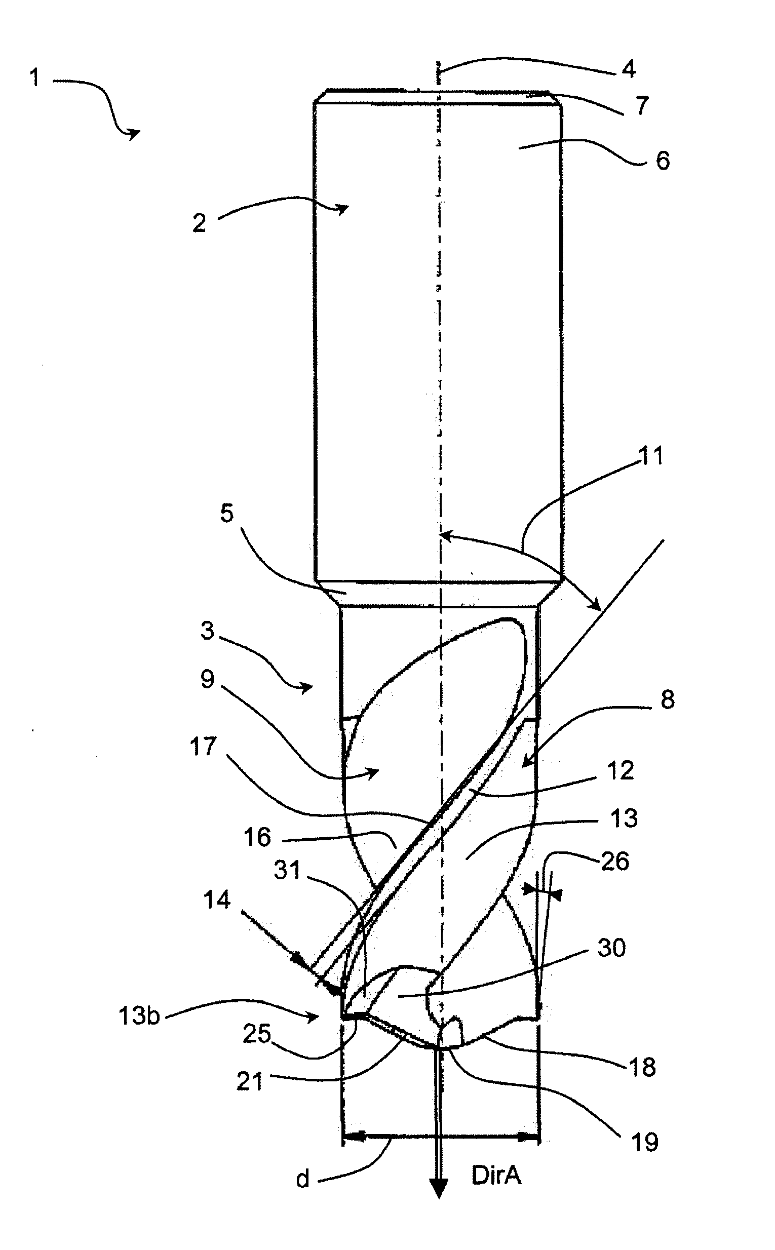
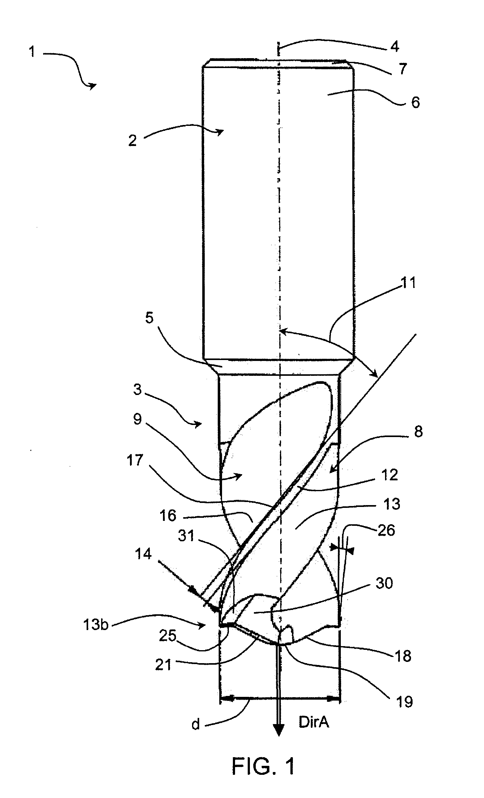
[0024]FIGS. 1 to 5 represent by way of example a one-piece drill bit made of a ceramic for the high-speed drilling of composites, in particular carbon-fiber composites having an epoxy resin matrix.

[0025]This ceramic drill bit 1 comprises (see FIG. 1) a cylindrical or conical shank 2 and a body 3 extending from the shank along the axis 4 of the drill bit down to a free axial end 13b. The shank may be smooth, as illustrated here, or may have an annular slot (not shown) used for clamping the drill bit in the chuck of a machine tool (not shown). The free axial end 6 of the shank terminates in a bevel 7, making it easier to insert it into the chuck of the machine tool. The shank 2 and the body 3 of the drill bit 1 may be joined together via a bevel 5, this being necessary when the outside diameter of the shank differs from that of the body.

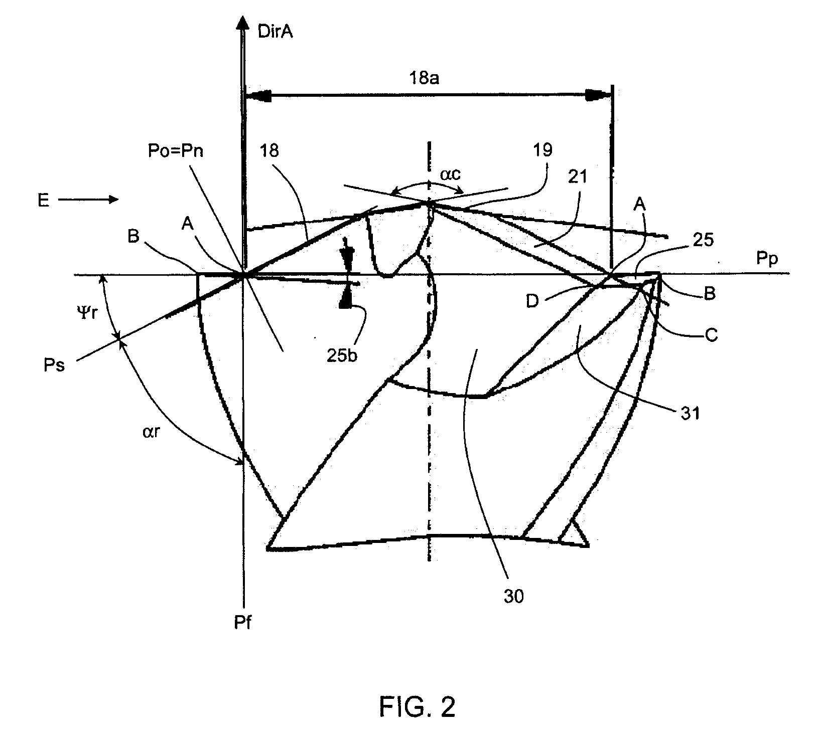
[0026]The body 3 of the drill bit 1 includes two lips 8 and two flutes 9 extending alternately around the axis 4 from the shank 2 down to the free axi...


PUM

PropertyMeasurementUnit
helix angleaaaaaaaaaa
conicity angleaaaaaaaaaa

Abstract

The ceramic drill bit has a particular geometry and is very advantageously applicable to the very high-speed drilling of parts made of a composite, especially a carbon-fiber composite having an epoxy resin matrix. The invention also relates to a method for the high-speed drilling of composites.

Description

BACKGROUND OF THE INVENTION[0001]The invention relates to a ceramic drill bit and is particularly applicable to the very high-speed drilling of parts made of a composite, especially a carbon-fiber composite having an epoxy resin matrix. This type of composite, thanks to its high mechanical properties and its low density, is widely used in fields such as the aeronautical field.DESCRIPTION OF THE PRIOR ART[0002]At the present time, ceramics, owing to their high hardness and their very high temperature resistance, are being developed for the manufacture of cutting tools. Known ceramic cutting tools, such as those described in patent document EP 0 477 093, are generally milling cutter or turning tools and enable high-speed machining operations to be carried out on very hard materials. However, the possible constraints on a drill bit (drilling depth, removal of the chips, intensity and direction of the cutting forces) during a drilling operation are greater than those that may be applied...

Claims


Application Information

Patent Timeline
Patent Type & Authority Applications(United States)
IPC IPC(8): B23B35/00B23B27/14B23B51/02
CPCB23B51/0081Y10T408/78B23B2215/04B23B2226/18B23B2226/27B23B2226/275B23B2226/36B23B2251/04B23B2251/14B23B2251/18B23B2270/54Y10T408/899Y10T408/9097Y10T408/03B23B51/02
Inventor TURRINI, CLAUDE
Owner SN DETUDE & DE CONSTR DE MOTEURS DAVIATION S N E C M A
Why Eureka
Try Eureka