Antioxidant doping of crosslinked polymers to form non-eluting bearing components

a crosslinked polymer and antioxidant technology, applied in the field of antioxidant doping of crosslinked polymers, to achieve the effect of improving the oxidation properties of crosslinked materials and increasing wear properties

Inactive Publication Date: 2009-01-29
BIOMET MFG CORP
View PDF101 Cites 79 Cited by
  • Summary
  • Abstract
  • Description
  • Claims
  • Application Information

AI Technical Summary

Benefits of technology

[0003]Crosslinked polymers such as ultra high molecular weight polyethylene (UHMWPE) have found wide application in medical implants as bearing components. The crosslinked polymers exhibit favorable wear properties and have good bio-compatibility. In addition to good wear properties, it is also important to provide materials that resist oxidation so that the life of the material in the body can be increased.
[0004]A variety of techniques has been used to increase the oxidation stability of crosslinked materials such as UHMWPE. In some, a series of heat treatment steps is performed on the crosslinked material to decrease or eliminate the free radicals induced by the crosslinking. Recently, techniques have been developed to incorporate an antioxidant material such as vitamin E directly into the bulk material.
[0007]In various embodiments, the present technology provides polymeric materials such as UHMWPE suitable for use as bearing components in medical implants. Such implants may be used in hip replacement, knee replacements, and the like. The polymeric material is preferably crosslinked to increase its wear properties. The crosslinked polymeric material is treated by in-diffusion of antioxidant compositions that serve to or eliminate trap free radicals in the bulk material. As a result, the oxidation properties of the crosslinked material are improved. Antioxidants include, without limitation, vitamin E or tocopherols and carotenoid antioxidants, triazine antioxidants, and the like.

Problems solved by technology

To incorporate an antioxidant material into a bulk polymer, a challenge is to provide a significant amount of antioxidant in the interior of the material while maintaining an acceptable non-leaching value of antioxidant on the surface.

Method used


Image

  • Antioxidant doping of crosslinked polymers to form non-eluting bearing components
  • Antioxidant doping of crosslinked polymers to form non-eluting bearing components
  • Antioxidant doping of crosslinked polymers to form non-eluting bearing components

Examples


example 1

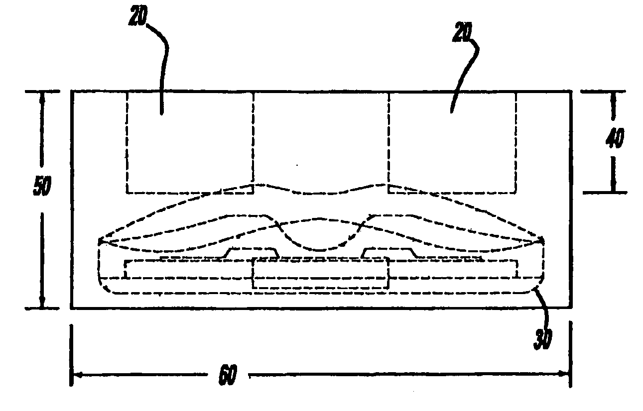
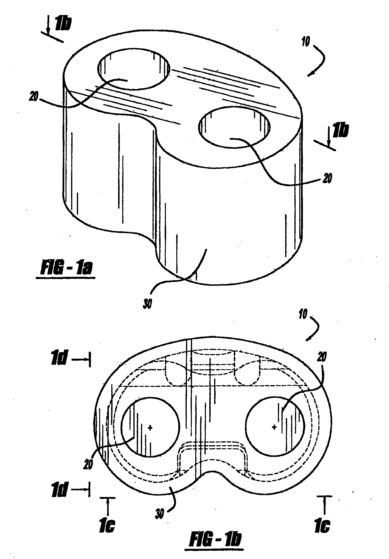
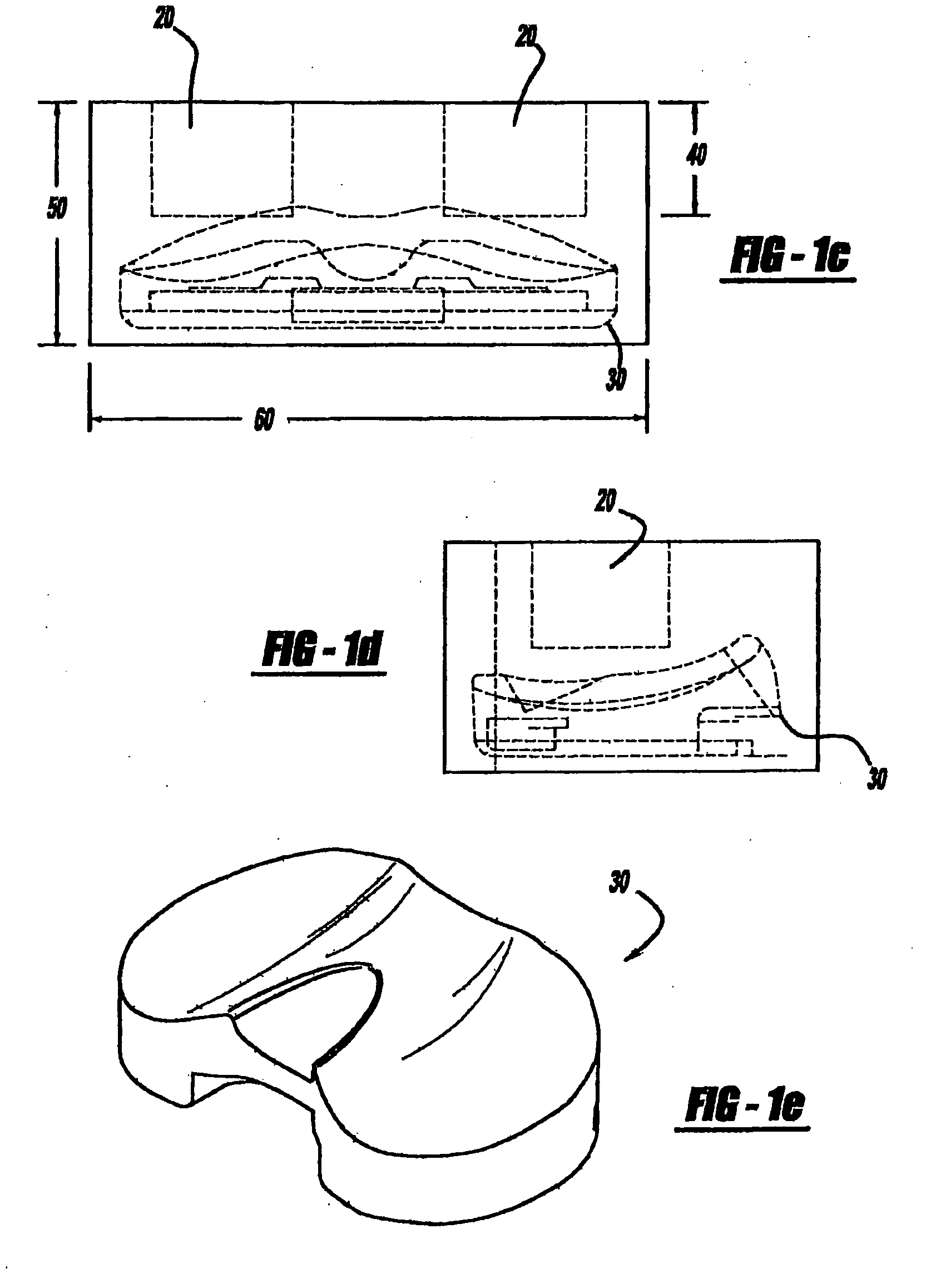
[0071]FIG. 1a shows a perspective view of a tibial preform 10 characterized by an overall kidney shape and containing two non-through holes 20. FIG. 1b shows a plan view of the top of the preform 10. Hidden lines indicate schematically the rough position of a tibial bearing 30 to be machined out of the preform 10. FIG. 1c is a plan view showing the depth 40 of the non-through holes 20 and the height 50 and length 60 of the preform 10. FIG. 1d is another side plan view showing the non-through holes 20 and the hidden lines of the tibial bearing 30. FIG. 1e is a perspective of the tibial bearing 30 prepared by machining the preform.

[0072]The views of FIG. 1 illustrate the preform in relation to the implant component machined from it. A line from the surface 70 of the preform to the component 30, when drawn in its shortest length, will be, in various embodiments, 1-15 mm, 1-10 mm, or 1-4 mm in length. Put another way, the outer surface of the component is within 15 mm of the outer surfa...

example 2

[0073]Preparing an implant component involves the following steps:

[0074]An acetabular preform is machined from UHMWPE barstock. A typical preform is shown in FIG. 1a.

[0075]The preform is then cleaned in isopropyl alcohol, placed in a barrier film bag, the bag is placed in a chamber which evacuates the air, purges with argon, evacuates the argon and then seals the package.

[0076]The preforms are then boxed in a double layer and sent for gamma irradiation to a dose of 100±10 kGy.

[0077]When the preforms return, they are removed from the barrier film packaging and doped in vitamin E (dl-α-tocopherol) for 8 hours at 122° C.

[0078]At the end of the doping cycle, the excess vitamin E is cleaned from the surface.

[0079]The preforms are then placed in an inert gas oven and heated to 130° C. and the temperature is held for 264 hours. At the end of the 264 hours, the oven is cooled to room temperature over 6 hours.

[0080]FTIR testing is used to quantify the amount of vitamin E in the polyethylene...

example 3

[0085]Equipment for measuring vitamin E or other antioxidant index includes an FTIR spectrometer, a microtome capable of 200 μm thick slices, an ir microscope with automated stage, and computer software capable of collecting spectra across a sample and creating a profile of peak area ratios for two specific peaks. Measuring the index of a part such as an implant component or a preform involves the following steps:[0086]1. Cut the part such that the area farthest from all surfaces is exposed. This will be the area with the lowest concentration of vitamin E.[0087]2. Use the microtome to make a 200 μm thick slice of the preform. The cut direction is perpendicular to the measurement direction. (The measurement direction is generally the shortest distance between two surfaces that passes through the area with the lowest vitamin E concentration.)[0088]3. Secure the sample to a slotted metal slide with magnets such that the measurement direction is parallel to the slot.[0089]4. Place the s...


PUM

PropertyMeasurementUnit
temperatureaaaaaaaaaa

Abstract

Methods provide a non-eluting antioxidant doped UHMWPE in the form of an implant bearing component. The process includes the steps of: (a) providing a preform; (b) irradiating the preform with γ-irradiation to crosslink the UHMWPE; (c) doping the crosslinked preform by exposing it to an antioxidant composition at a temperature below the melting point of the UHMWPE; (d) removing the doped material from contact with the antioxidant composition; and then (e) annealing by heating the doped material at a temperature above 30° C. and below the melting point of the UHMWPE; followed by (f) making an implant bearing component from the doped material, wherein at least 1 mm but no more than about 15 mm of material are removed to make the component.

Description

CROSS-REFERENCE TO RELATED APPLICATION[0001]This application claims the benefit of U.S. Provisional Application Ser. No. 60 / 952,452 filed Jul. 27, 2007, the disclosure of which is incorporated herein by reference.INTRODUCTION[0002]The present technology relates to antioxidant doping of crosslinked polymers. Specifically, the technology relates to processes for incorporating antioxidant materials into crosslinked polymers for use in medical implants.[0003]Crosslinked polymers such as ultra high molecular weight polyethylene (UHMWPE) have found wide application in medical implants as bearing components. The crosslinked polymers exhibit favorable wear properties and have good bio-compatibility. In addition to good wear properties, it is also important to provide materials that resist oxidation so that the life of the material in the body can be increased.[0004]A variety of techniques has been used to increase the oxidation stability of crosslinked materials such as UHMWPE. In some, a s...

Claims


Application Information

Patent Timeline
Patent Type & Authority Applications(United States)
IPC IPC(8): A61F2/30B29C35/08
CPCA61F2/32A61F2/38A61L27/16B29C71/02B29C71/04B29C2035/085B23P15/003B29L2031/7532B29C2071/022A61F2/389A61F2/34C08L23/06
Inventor SCHROEDER, DAVID W.FREEDMAN, JORDAN H.
Owner BIOMET MFG CORP
Why Eureka
Try Eureka