Apparatus and method for high efficiency isolated power converter

a technology of isolated power converters and power converters, applied in the field of switching power converters, can solve the problems of less efficiency, increased demand in the field of power conversion-size reduction, and difficulty in meeting high-efficiency with the present available power converters

Inactive Publication Date: 2009-02-05
LUMENIS LTD
View PDF4 Cites 133 Cited by
  • Summary
  • Abstract
  • Description
  • Claims
  • Application Information

AI Technical Summary

Benefits of technology

[0009]The present invention, in embodiments described hereinafter, may offer one, some, or all of the following advantages and features:
[0013]4. High efficiency due to low switching and conductive losses.

Problems solved by technology

The increased demand in the field of power conversion-size reduction and high-efficiency is difficult to meet with the present available power converters.
Some features inherent in devices of relevant technology militate against achievement of the desired goals.
Some converters are specifically designed to handle a wide range of output loads and variations of input voltage, resulting in less efficiency.
Reducing the size of components (capacitors and magnetic component) related to high switching frequency and as results to concomitant high switching losses.
However, the operation with typical pulse width modulation or the variation of switching frequency is a deficient in full volume of line and maximal load alternation which leads to stresses on the switching devices which are similar to those of a hard switched converter.
However, the operation in full volume (from 0 to max) of loads and line variation leads to inevitable hard switching, e.g., excessive switching losses, excessive EMI and the like.
However, high current switching leads to high level conductive and switching losses, and causes the limitation to power, obstacles to decrease the cost, volume and EMI.

Method used


Image

  • Apparatus and method for high efficiency isolated power converter
  • Apparatus and method for high efficiency isolated power converter
  • Apparatus and method for high efficiency isolated power converter

Examples


Embodiment Construction

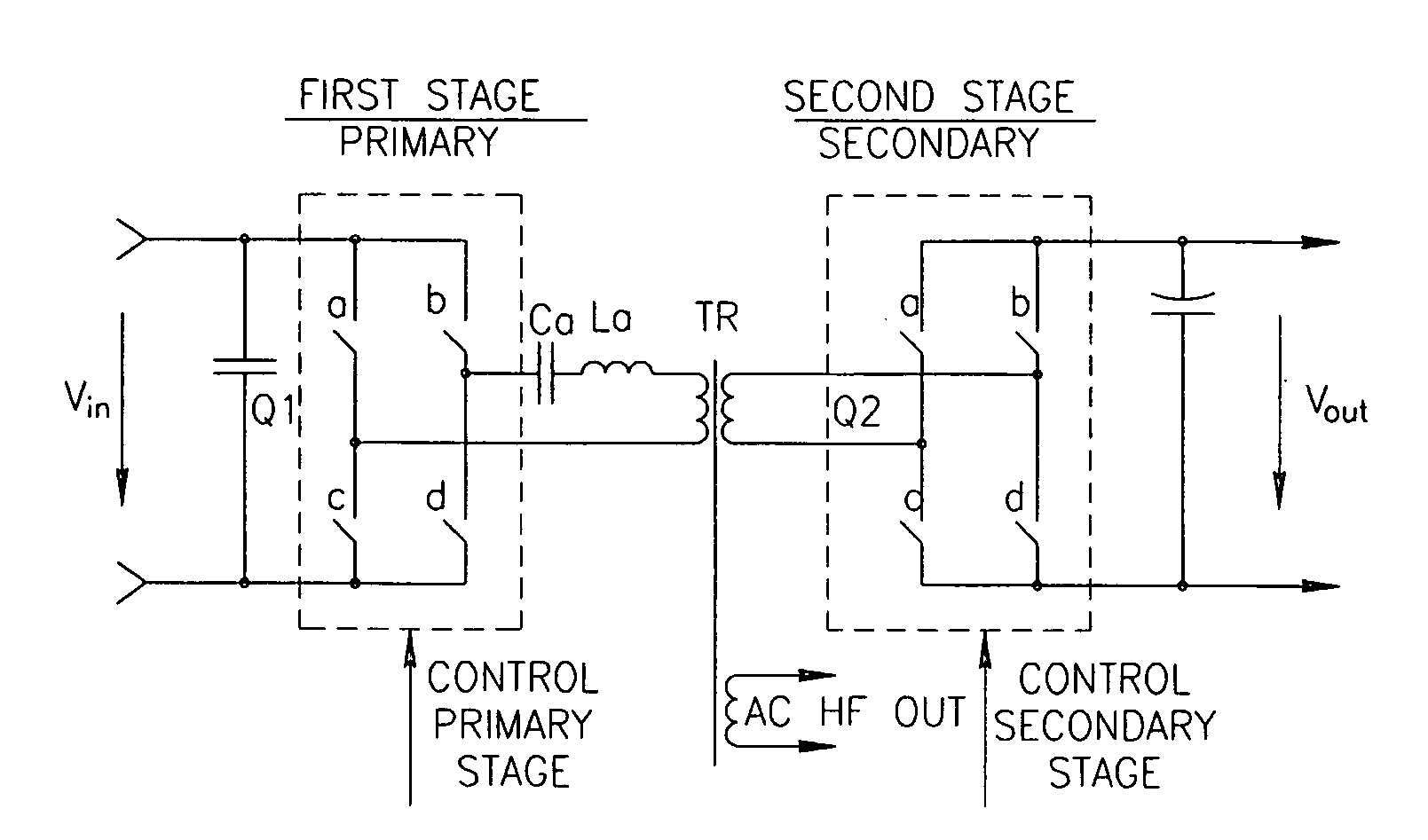
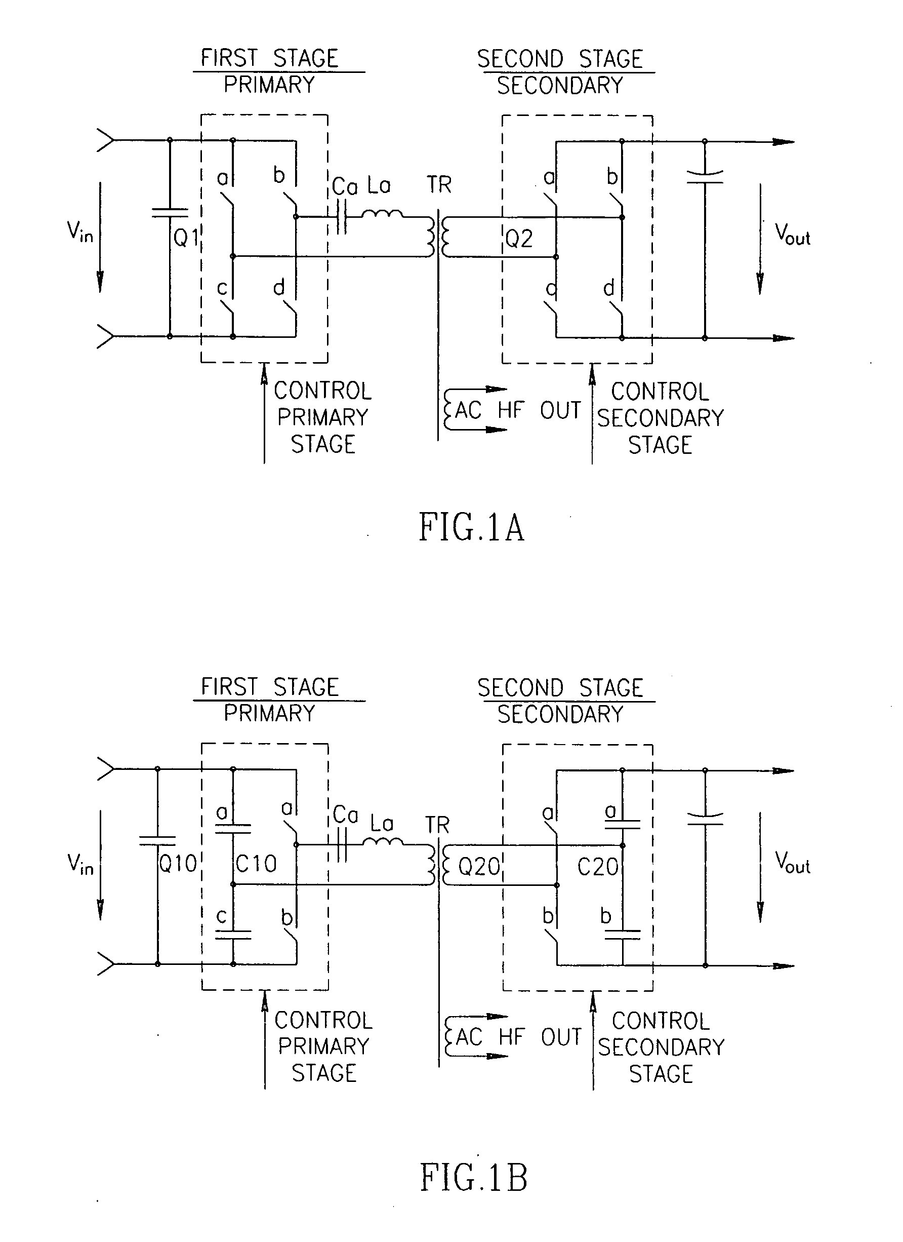
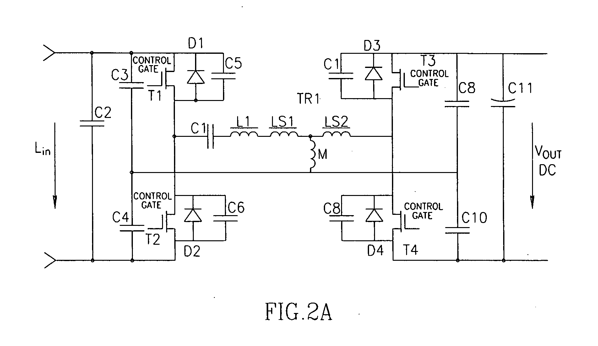
[0026]The invention described herein after pertains to an electrically isolated DC-DC converter that may be used to deliver power of DC voltage or AC voltage (high frequency of up to, for example, 1 MHz yet the operational frequency high range may get higher as the technology of production of switching transistors improves) from a DC source such as a battery or rectifier utility. In such a converter, a transformer may be used to provide electrical isolation and a step-down or step-up in voltage level, according to its ratio, as may be required. Switching means (such as transistors, preferably MOSFET) and diodes, preferably of the fast recovery type may be used in conjunction with capacitors and inductors to induce non-DC current (i.e. AC or pulsating current) in the primary circuit to activate a transformer to create the required conversion. A control circuit may typically be included to provide the required driving signals to the transistor control terminals. The ability to provide...


PUM


Abstract

A DC-DC converter apparatus comprising half or full bridge, two-stage resonant converter, which may include series resonant (inductor, capacitor) devices. An isolated transformer having primary and secondary winding supplies current to full-wave secondary stage-bridge through the use of primary winding resonant devices employing primary stage-bridge. The magnetizing of said devices employs zero-current, zero-voltage resonant-transition switching technology, which reduces switching losses at all switching frequencies to almost zero. The regulation of output voltage at all loads and input voltages achieved by the control of the switching frequency and the phase between signals for primary and secondary stages. The proper intermittent of the frequency and the phase allows achieving the value of efficiency up to 97%.

Description

FIELD OF THE INVENTION[0001]This invention relates generally to a switching power converter and, more specifically, to a two-stage converter with transformer separation having improved zero voltage switching (ZVS) and zero current switching (ZCS) operation modes.BACKGROUND OF THE INVENTION[0002]The increased demand in the field of power conversion-size reduction and high-efficiency is difficult to meet with the present available power converters. Some features inherent in devices of relevant technology militate against achievement of the desired goals. Some converters are specifically designed to handle a wide range of output loads and variations of input voltage, resulting in less efficiency. Reducing the size of components (capacitors and magnetic component) related to high switching frequency and as results to concomitant high switching losses.[0003]Common approach of ZVS and ZCS topology disclosed in the prior art is series resonant converter described in e.g. USOORE33866E, U.S....

Claims


Application Information

Patent Timeline
Patent Type & Authority Applications(United States)
IPC IPC(8): H02M3/335
CPCH02M3/33592H02M3/337Y02B70/1491Y02B70/1475H02M2001/0058Y02B70/1433Y02B70/10H02M1/0058H02M3/33573H02M3/33571H02M3/01
Inventor LEV, DUBITSKY
Owner LUMENIS LTD
Why Eureka
Try Eureka