
Fuel cell system and method for operating the same

a fuel cell and system technology, applied in the field of fuel cell systems, can solve the problems of reducing the amount of cathode gas (air flow rate) to be introduced to the diluter provided downstream of the purge valve through the cathode, and reducing the concentration of hydrogen

Active Publication Date: 2009-02-05
HONDA MOTOR CO LTD
View PDF4 Cites 21 Cited by
  • Summary
  • Abstract
  • Description
  • Claims
  • Application Information

AI Technical Summary

Benefits of technology

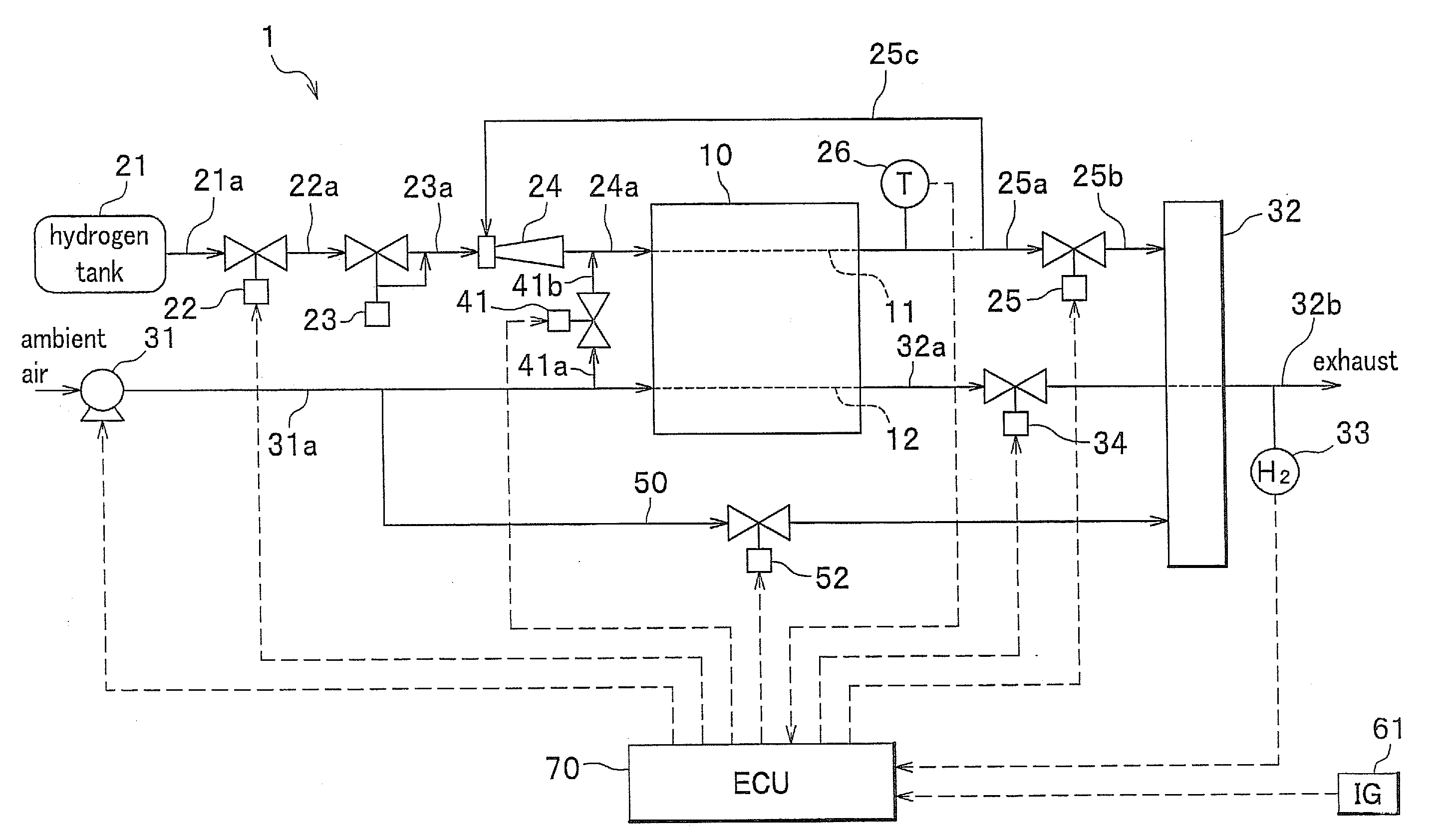
[0011]In one aspect of the present invention, there is provided a fuel cell including a fuel gas channel on an anode side and an oxidant gas channel on a cathode side which is configured to generate electricity using a fuel gas supplied to the fuel gas channel and an oxidant gas supplied to the oxidant gas channel; a diluting unit configured to dilute gas discharged from the fuel gas channel by mixing the discharged gas with a dilution gas which is supplied from an oxidant gas supply unit and passed through and discharged from the fuel cell, and to exhaust the diluted gas to outside; a purge valve configured to purge gas in the fuel gas channel to the diluting unit; a scavenging unit configured to scavenge the fuel gas channel and the oxidant gas channel; and a dilution assist unit configured to supply a dilution assist gas to the diluting unit through an assist passage connected to the diluting unit to assist dilution in the diluting unit, during scavenging by the scavenging unit. With this configuration, for example, even when the purge valve is activated and gas in the fuel gas channel is purged during a halt of electricity generation, a fuel gas (hydrogen) of high concentration is prevented from being exhausted from the diluting unit, since the dilution is assisted by a dilution assist gas supplied from the dilution assist unit.
[0012]According to the present aspect, even when the gas in the fuel gas channel is discharged during scavenging, by activating the dilution assist unit to supply a dilution assist gas, an amount of gas for dilution in the diluting unit can be steadily ensured. In addition, though water produced from electricity generation remains in the diluting unit, the flow rate of the gas supplied to the diluting unit increases, and therefore, the produced water stored in the diluting unit can be steadily exhausted to outside, enhancing water-discharge efficiency. Accordingly, even when the fuel cell system of the present invention is used, for example, in a low-temperature environment (e.g., below zero), the produced water in the fuel cell, the diluting unit and the like are prevented from being frozen, ensuring immediate startup in a low-temperature environment.
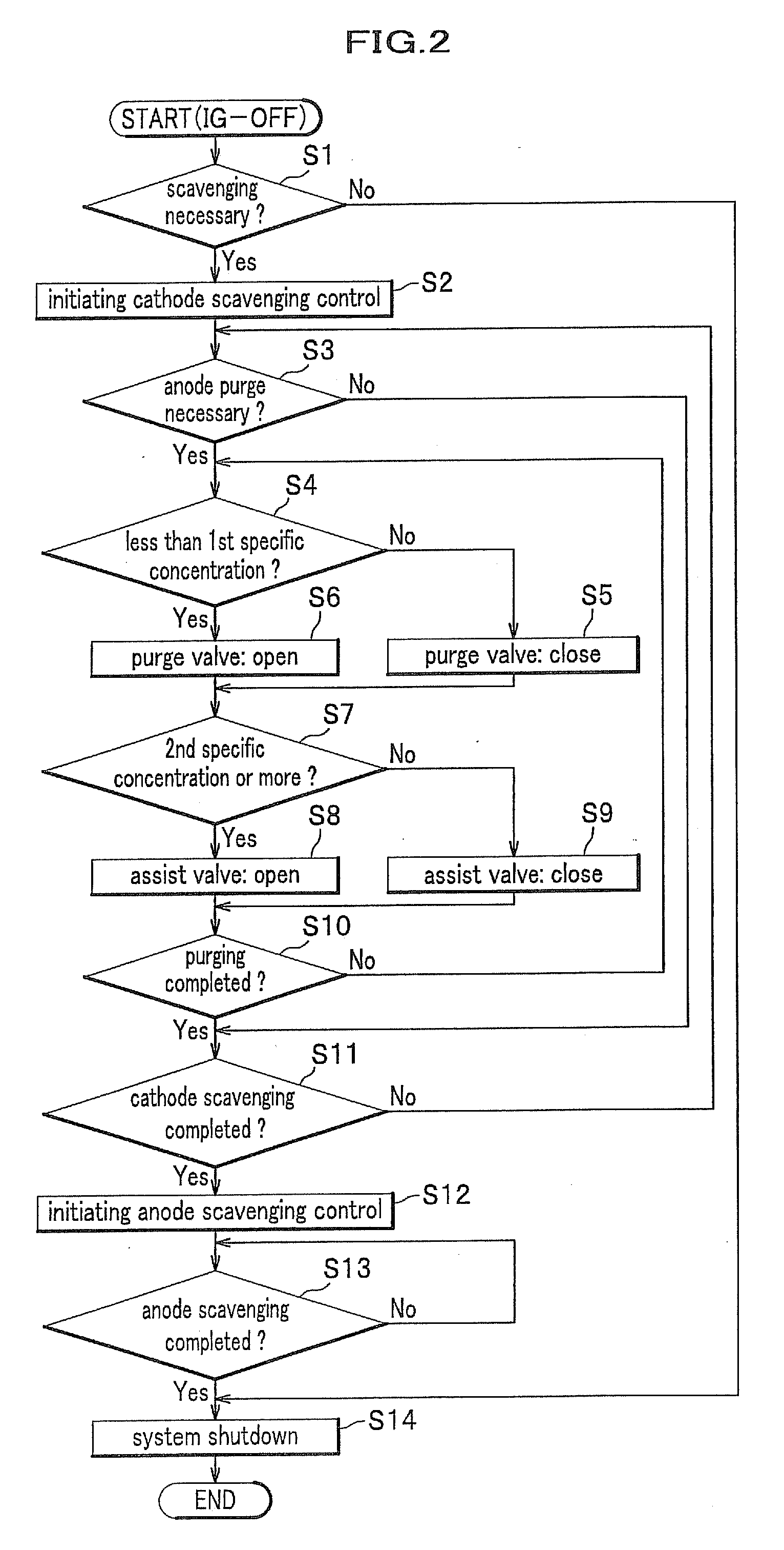
[0013]In the present invention, it is preferable that the fuel cell system further includes a concentration detector configured to detect a concentration of hydrogen contained in gas exhausted from the diluting unit, and when a concentration of hydrogen exhausted from the diluting unit detected by the concentration detector is less than a second specific concentration which is below an upper limit value (upper limit concentration), the supply of the dilution assist gas from the dilution assist unit to the diluting unit is stopped. According to the present aspect, when the concentration of hydrogen exhausted from the diluting unit is less than the second specific concentration, the supply of the dilution assist gas is stopped. Therefore, by performing the dilution assist only when it is necessary, it becomes possible to reduce power consumption, for example, during the dilution assist, and at the same time, to reduce noise during the assist.

Problems solved by technology

When a fuel cell mounted on a vehicle or the like is used in a low-temperature environment (e.g., below zero), residual water (produced water) may be frozen and may damage a solid polymer electrolyte membrane and the like.
Therefore, when the purge valve is opened and hydrogen purging is performed, there arises a problem that an amount of the cathode gas (air flow rate) to be introduced to the diluter provided downstream of the purge valve through the cathode is reduced, and that a concentration of hydrogen exhausted from the diluter is increased.

Method used


Image

  • Fuel cell system and method for operating the same
  • Fuel cell system and method for operating the same
  • Fuel cell system and method for operating the same

Examples


Embodiment Construction

[0034]Embodiments of the present invention will be described in detail below with reference to the accompanying drawings.

[0035]In the present embodiment, descriptions will be made while illustrating an automobile, to which a fuel cell system is applied. However, the application of the fuel system is not limited to the automobile, and it may be applied to other types of vehicle systems, such as airplane and ship, or to a stationary system as a household power source.

[0036]In the present specification, the term “dilution assist” implies effects obtained by supplying a dilution assist gas into a diluter, i.e., not only an effect of assisting hydrogen dilution, but also an effect of pushing out gas in the diluter.

[0037]A fuel cell system 1 according to a present embodiment shown in FIG. 1 is mounted on a fuel cell vehicle (moving body, not shown). The fuel cell system 1 includes: a fuel cell stack 10; an anode system (fuel gas supply unit) for supplying hydrogen (fuel gas) to an anode o...


PUM

PropertyMeasurementUnit
temperatureaaaaaaaaaa
concentrationaaaaaaaaaa
concentration detectoraaaaaaaaaa

Abstract

A fuel cell system including: a fuel cell including a fuel gas channel and an oxidant gas channel, which is configured to generate electricity using a fuel gas and an oxidant gas; a diluting unit configured to dilute gas discharged from the fuel gas channel by mixing the discharged gas with a dilution gas which is supplied from an oxidant gas supply unit and passed through and discharged from the fuel cell, and to exhaust the diluted gas to outside; a purge valve configured to purge gas in the fuel gas channel to the diluting unit; a scavenging unit configured to scavenge the fuel gas channel and the oxidant gas channel; and a dilution assist unit configured to supply a dilution assist gas to the diluting unit through an assist passage connected to the diluting unit to assist dilution in the diluting unit, during scavenging by the scavenging unit.

Description

CROSS-REFERENCE TO RELATED APPLICATIONS[0001]This application claims the foreign priority benefit under Title 35, United States Code, section 119 (a)-(d), of Japanese Patent Application No. 2007-202853, filed on Aug. 3, 2007 in the Japan Patent Office, the disclosure of which is herein incorporated by reference in its entirety.BACKGROUND OF THE INVENTION[0002]1. Field of the Invention[0003]The present invention relates to a fuel cell system in which scavenging is performed during, for example, a halt of electricity generation by a fuel cell, and a method for operating the same.[0004]2. Description of the Related Art[0005]Recently, studies have been widely made to develop a fuel cell, such as polymer electrolyte fuel cell (PEFC), in which electricity is generated using hydrogen (fuel gas) supplied to an anode and oxygen-containing air (oxidant gas) supplied to a cathode. Such a fuel cell is formed by stacking a plurality of single cells, each formed by sandwiching a solid polymer ele...

Claims


Application Information

Patent Timeline
Patent Type & Authority Applications(United States)
IPC IPC(8): H01M8/04H01M8/02
CPCH01M8/04179H01M8/04231Y02E60/50H01M8/04462H01M8/04753H01M8/04253
Inventor WAKE, CHIHIROMIYATA, KOICHIRO
Owner HONDA MOTOR CO LTD
Learn More