Intermediate transfer member, method of manufacturing intermediate transfer member, and image forming apparatus

a transfer member and intermediate technology, applied in the field of intermediate transfer members, can solve the problems of insufficient transfer efficiency and tendency to generate image failure caused by transfer failure of toner image, and achieve the effects of excellent release properties, excellent durability, and improved transfer efficiency

Active Publication Date: 2009-02-12
KONICA MINOLTA BUSINESS TECH INC
View PDF13 Cites 17 Cited by
  • Summary
  • Abstract
  • Description
  • Claims
  • Application Information

AI Technical Summary

Benefits of technology

[0019]The following effects can be produced via the present invention. That is, by utilizing an intermediate transfer member comprising a substrate and provided thereon, a surface layer comprising at least a layer, wherein the substrate has a universal hardness of 50-190 N/mm2, and the surface layer has a surface hardness of 3-11 GPa measured in accordance with a nanoindentation method, that is described in Structure 1, provided can be the intermediate transfer member exhibiting an excellent releasing property with toner, together with improved transfer efficiency and excellent durability.
[0020]Also provided can be a manufacturing apparatus of the intermediate transfer member in which no large-scale equipment such as a vacuum evaporator or the like is installed, exhibiting an excellent releasing property with toner, together with improved transfer efficiency and excellent durability by utilizing a method of manufacturing the intermediate transfer member, comprising the step of forming at least an outermost layer of the surface layer on the substrate by an atmospheric pressure plasma CVD method, wherein the at least an outermost layer has a carbon atom content of 20 atomic percent or less, d

Problems solved by technology

However, in the case of a superimposing transfer system fitted with this intermediate transfer member, image failure caused by transfer failure of a toner image tends to be generated since transferring twice such as the primary transfer and the secondary transfer is conducted, and four color toners are also superimposed on the intermediate transfer member.
However, there is a problem suc

Method used


Image

  • Intermediate transfer member, method of manufacturing intermediate transfer member, and image forming apparatus
  • Intermediate transfer member, method of manufacturing intermediate transfer member, and image forming apparatus
  • Intermediate transfer member, method of manufacturing intermediate transfer member, and image forming apparatus

Examples


example

[0170]Next, the present invention will now be specifically described referring to examples, but embodiments of the present invention are not limited thereto.

1. Preparation of Sample

[0171]Three kinds of substrates A, B and C were prepared as described below.

(Substrate A)Polyphenylenesulfide resin “E2180”100parts by weight(produced by Toray Co., Ltd.)Conductive filler “Furnace #3030B”16parts by weight(produced by Mitsubishi Chemical Corp.)Graft copolymer “MODIPER A4400”1part by weight(produced by Ninon Yushi Co., Ltd.)Lubricant (calcium montanate)0.2parts by weight

[0172]The above-described composition was put into a single-axis extruder, and molten and kneaded to prepare a resin mixture. The resin mixture was extruded into a seamless belt shape through a ring shaped die having a seamless belt-shaped discharge opening attached at the end of the extruder. The extruded seamless belt-shaped resin mixture was introduced into a cooling cylinder provided at a discharging opening, and cooled ...


PUM

PropertyMeasurementUnit
Thicknessaaaaaaaaaa
Pressureaaaaaaaaaa
Pressureaaaaaaaaaa

Abstract

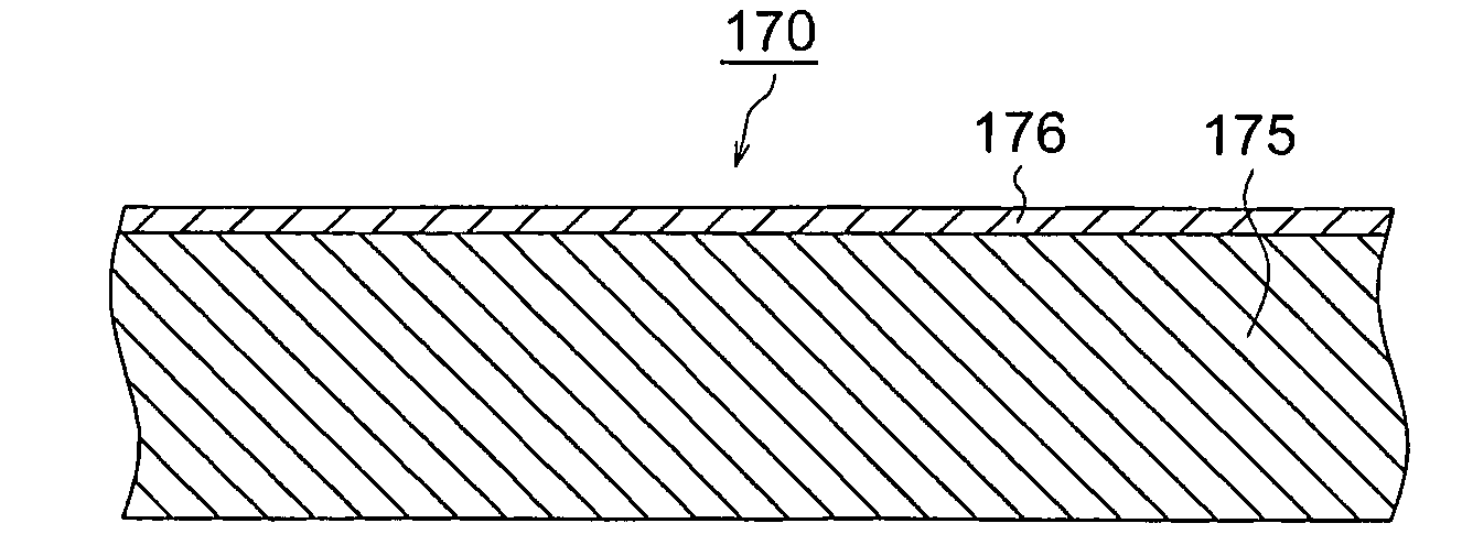
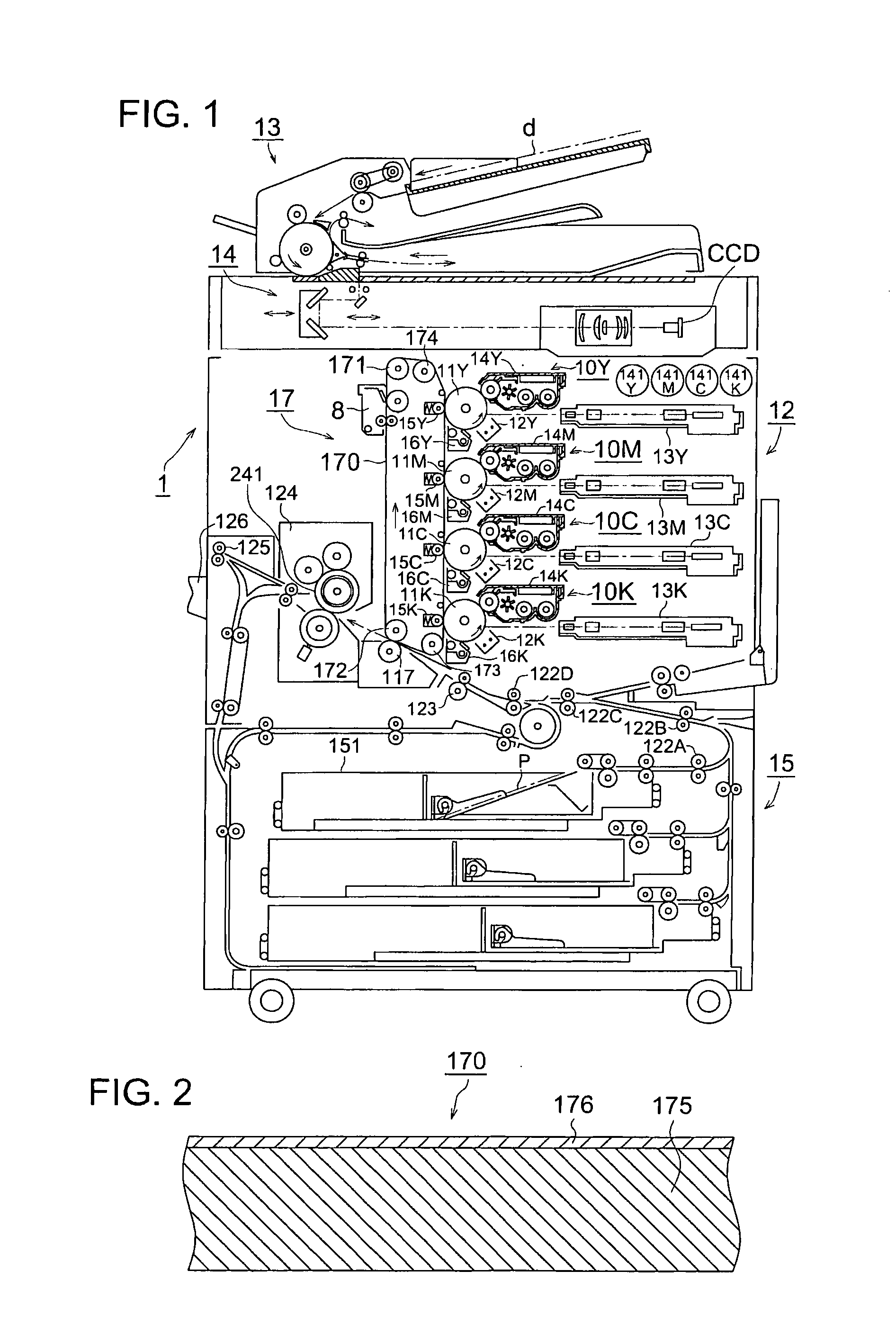
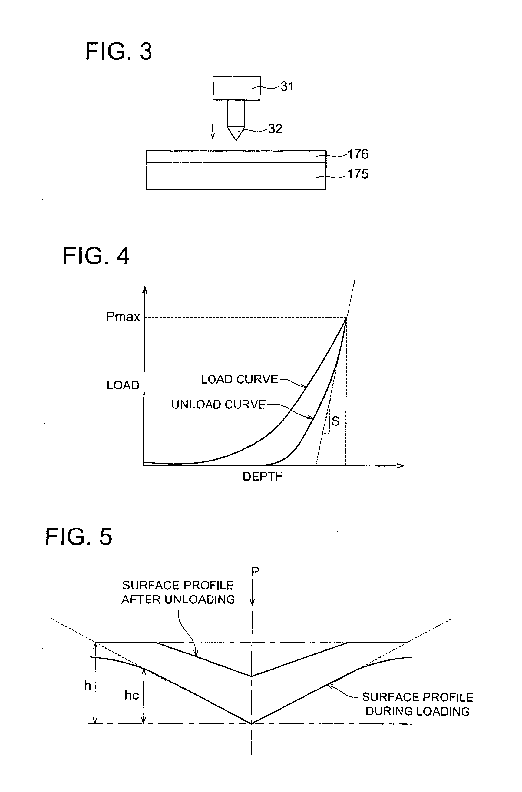
An objective is to provide an intermediate transfer member exhibiting higher transferability together with higher cleaning ability and durability, a manufacturing apparatus of an intermediate transfer member in which no large-scale equipment such as a vacuum evaporator or the like is installed, and an image forming apparatus fitted with the intermediate transfer member. Also disclosed is intermediate transfer member 170 possessing substrate 175 and surface layer 176 composed of at least one layer provided on the surface of substrate 175, wherein foregoing substrate 175 has a universal hardness of 50-190 N/mm2, and foregoing surface layer 176 has a surface hardness of 3-11 GPa measured in accordance with a nanoindentation method.

Description

TECHNICAL FIELD[0001]The present invention relates to an intermediate transfer member, a method of manufacturing the intermediate transfer member and an image forming apparatus fitted with the intermediate transfer member to be transferred by synthesizing a toner image with respect to each of colors for a color image in electrophotographic apparatuses and electrostatic recording apparatuses such as an electronic copying machine, a laser beam printer, a facsimile machine and so forth.BACKGROUND[0002]In the past, as a method of transferring a toner image on an electrophotographic photoreceptor (hereinafter, also referred to simply as a photoreceptor) onto a recording material for a final image, there has been known a method of direct transfer of a toner image formed on an electrophotographic photoreceptor onto a recording material. On the other hand, there is known an image forming system, the system employing an intermediate transfer member, in which a transfer process of transferrin...

Claims


Application Information

Patent Timeline
IPC IPC(8): G03G15/20B32B7/02C23C16/513C08J7/043C08J7/046
CPCC08J7/045Y10T428/24983G03G15/162G03G2215/0135C08J7/0423C08J7/043C08J7/046
Inventor MAEHARA, YUICHIRO
Owner KONICA MINOLTA BUSINESS TECH INC
Why Eureka
Try Eureka