[0004]It is an object of the present invention to provide an electronic device including a digital oscillator with an improved accuracy and long term stability of oscillation frequency.
[0005]Accordingly, the present invention is an electronic device including a
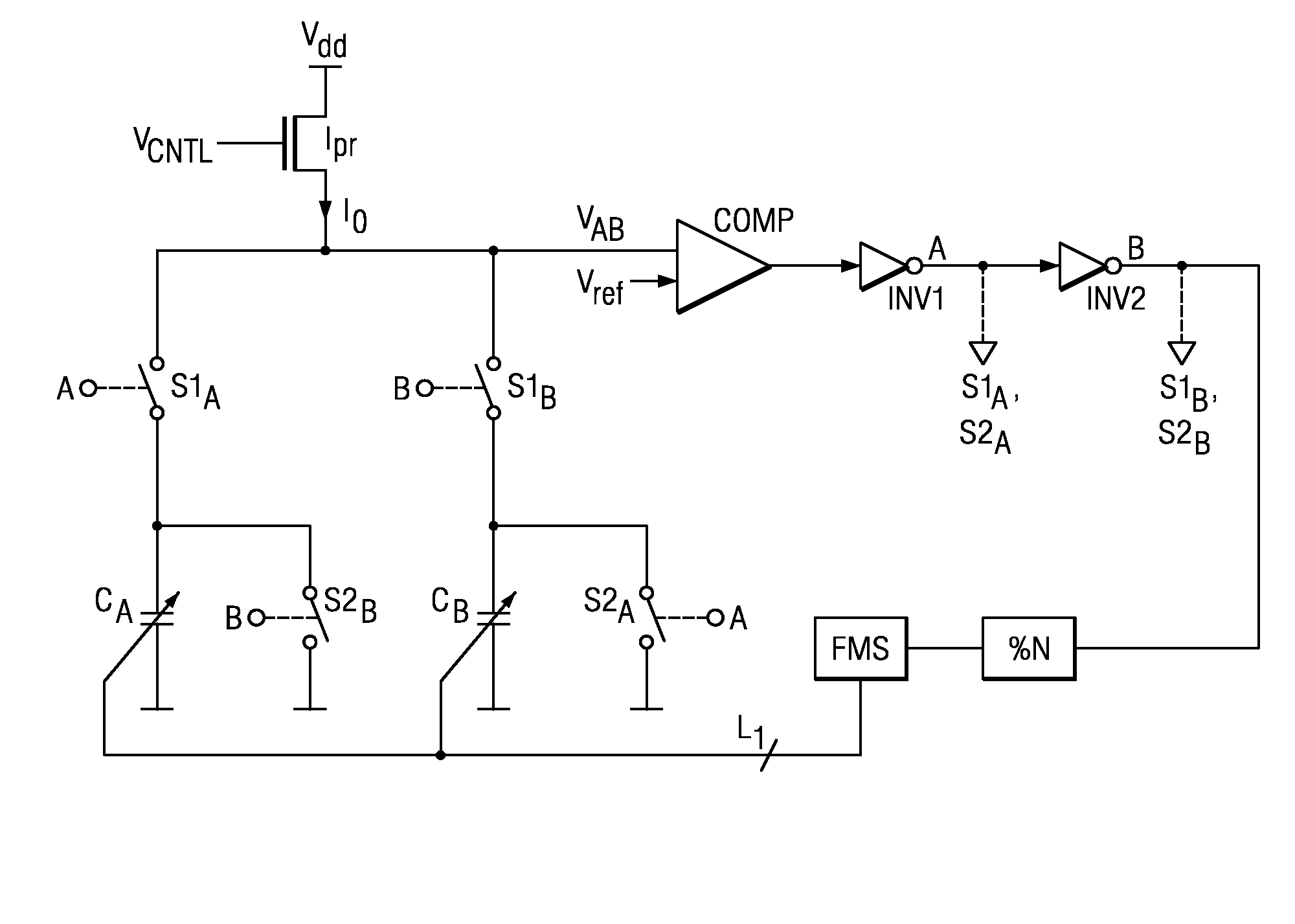
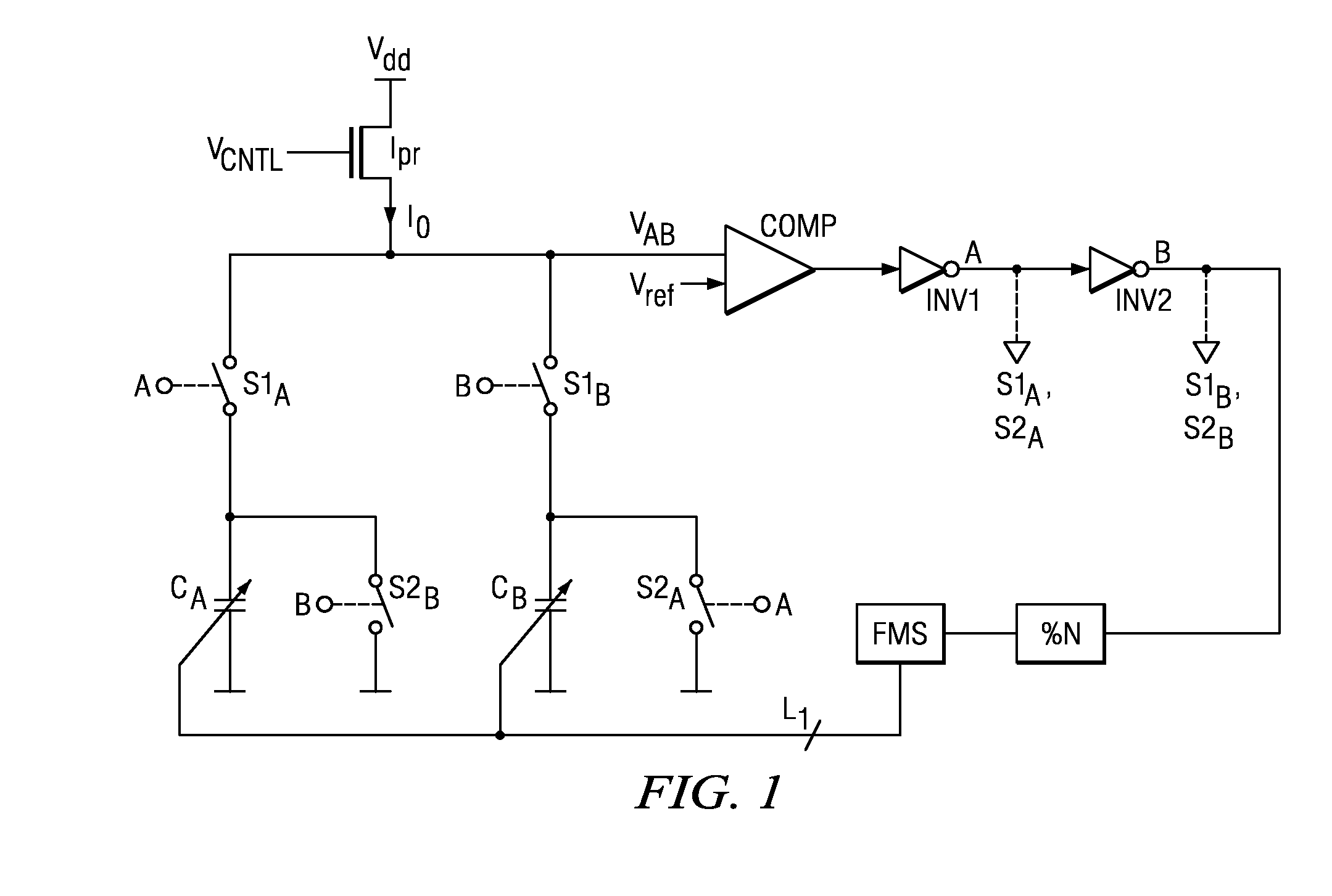
digital controlled oscillator. The digital controlled oscillator includes a programmable
current source, a first
variable capacitor and a second variable
capacitor. A
comparator compares the
voltage drop across the variable capacitors with a reference voltage level and provides a DCO output clock signal. A switch alternately charges the variable capacitors from the programmable current source or discharges the variable capacitors in response to an output signal of the comparator. A clock divider divides the DCO output clock signal by a factor N, which is substantially greater than 1. A frequency monitor receives the divided clock signal. The frequency monitor determines the
time difference of successive clock periods of the divided clock signal and generates a corresponding feedback signal. The DCO adjusts the DCO output clock frequency in response to the feedback signal. The DCO frequency may be advantageously varied by adapting the
capacitance values of the variable capacitors with the feedback signal. The factor N is preferably chosen such that a period of the divided clock signal is in proportion to a temperature, supply voltage or other degradation induced deviation of the DCO output clock signal. The monitor advantageously compares pairs of consecutive divided clock periods, comparing each divided clock period with a preceding divided clock period and with a following divided clock period. This ensures continuous, consistent and reliable control.
[0007]Accordingly, the present invention chooses the factor N in accordance with a temperature deviation and / or a supply voltage induced deviation or any similar slow deviation to be compensated. As long as the deviation is relatively slow compared with the oscillating frequency, the present invention provides a convenient, easy and effective means to scale the
frequency deviation in the oscillator output frequency. It is therefore a special aspect of the invention to
scale down a DCO output frequency in a range where a clock frequency of a downscaled clock signal can be used as an indicator for a
frequency deviation, which is much slower than the DCO clock frequency. The
frequency deviation is determined in a differential and self-regulating manner. Successive clock periods of the downscaled clock are compared with each other and the comparison result is used to adjust the DCO frequency.
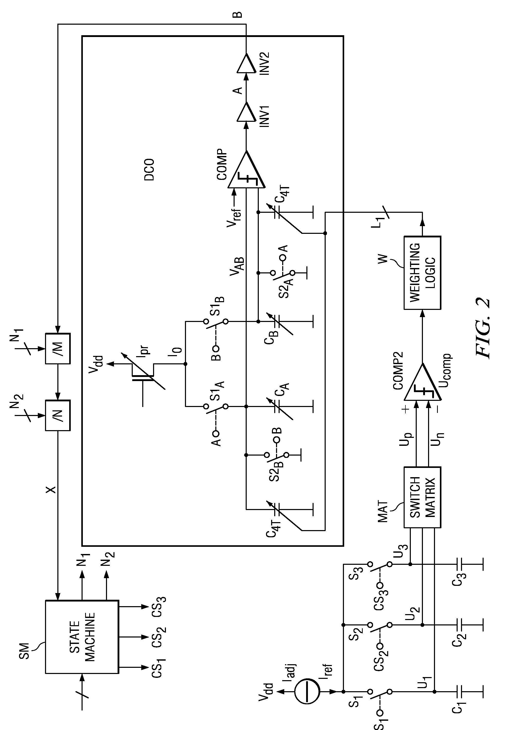
[0008]Preferably, the frequency monitor comprises an adjustable current source, three calibration capacitors, a comparator, and a switch to alternately couple one of the three calibration capacitors to the adjustable current source and the other two calibration capacitors to the second comparator in order to compare the voltage levels on the calibration capacitors. A controller controls the switch so that that one of the calibration capacitors is successfully charged with the current from the adjustable current source over a period of the divided clock signal to a respective maximum voltage level. Two maximum voltage levels are then consecutively selected and compared by the comparator in each clock period of the divided clock. A reference signal is generated by a voltage ramp. This voltage ramp is sampled by the oscillator output signal. The difference in amplitude of two successive samples is a measure of the
frequency drift or change. This drift is used as an input for a
digital control block implemented by the controller. The output of the controller then controls the three calibration capacitors. To optimize the tuning process, the
digital control block can use an
algorithm (e.g.
a search algorithm), for example a binary weighting scheme. This achieves both coarse and
fine tuning of the
feedback loop.
[0011]The present invention also provides a method for adjusting the oscillation frequency of a digital controlled oscillator. The method comprises dividing the frequency of the output clock signal of the DCO, comparing the length of successive periods of the divided clock signal and adjusting the output clock frequency of the DCO in response to the comparison. The
frequency drift of the DCO is mainly caused by limited power supply rejection (PSRR) of the oscillator and temperature / voltage drift of component parameters. The present invention establishes a self-control mechanism, wherein the instantaneous frequency of the DCO oscillating frequency is determined in successive points in time. The difference of these measurement results (i.e. the difference of the length or duration of the different periods) is directly proportional to the frequency change and is advantageously used in a control loop to reduce the error. Advantageously, a variable
capacitor in the DCO can be adjusted for tuning the frequency. Preferably pairs of consecutive clock periods of the divided clock signal are compared. Firstly, a first clock period of the divided clock signal is compared with a second clock period and next the second clock period is compared with a third clock period. Accordingly, each clock period of the divided clock signal is compared with a predecessor and a successor. This provides continuous and reliable control. The method of the present invention provides an
advantage in not using an
amplitude control loop or
phase locked loop scheme, where the oscillating frequency is compared with a reference signal. Instead, the circuit uses a mainly
digital tuning and trimming scheme in a feedback configuration, thereby establishing a self-controlling DCO. This allows a very simple and area-efficient implementation of a fast
acquisition scheme, due to the mainly digital realization of the circuitry. No complex low-frequency analog filters are required for the control loop. Furthermore, the present invention provides the advantages of a reliable operation. An area-efficient implementation is also provided, which has a wide
operating frequency range (e.g. 100 kHz to 40 MHz). Additionally, the adjustable current source providing current for the three capacitors can be implemented so as to be adjustable on the basis of the resistance of a single
resistor. If such a
resistor is implemented externally, i.e. not integrated with the other components on the same die, the high accuracy of the device depends only on an
external resistor and can be easily adjusted.

