Vacuum pump unit

a vacuum pump and vacuum pump technology, applied in machines/engines, liquid fuel engines, positive displacement liquid engines, etc., can solve the problems of reduced oil consumption, environmental pollution, and overload of main pumps, and avoid overload and corrosion of main pumps, preventing misconnection of pipes, and efficient piping operations

Inactive Publication Date: 2009-02-19
EBARA CORP
View PDF10 Cites 11 Cited by
  • Summary
  • Abstract
  • Description
  • Claims
  • Application Information

AI Technical Summary

Benefits of technology

[0011]The present invention has been made in view of the above drawbacks. It is therefore an object of the present invention to provide a low-noise vacuum pump unit which can realize a small and compact structure, sufficient ultimate pressure, low power consumption, no contamination due to oil or tip seals, no need for supply system of water or N2 gas, evacuation from atmospheric pressure in a short period of time, and no overload and no failure due to condensed water. Another object of the present invention is to provide a pump mount base for use in a vacuum pump unit which incorporates not only a mount base for vacuum pumps, but also pipes and valves to facilitate piping operations and to prevent misconnecting the pipes and valves.
[0034]According to the present invention, the magnet coupling action of the magnet rotors can allow the pump rotors to rotate synchronously in the opposite directions. Therefore, the need for using the timing gears can be eliminated, and an oil-free pump unit can thus be realized. Further, even if water vapor, contained in a gas, condenses on the pipe coupled to the main pump, the condensed water is prevented from flowing into the main pump. Therefore, overload and corrosion of the main pump can be avoided. Furthermore, by using the pump mount base, efficient piping operations can be realized and misconnecting of the pipes can be prevented. In addition, because the vacuum pump unit uses less components, a low cost can be achieved.

Problems solved by technology

However, this type of pump presents several problems including back diffusion of oil vapor into a vacuum chamber (contamination of the vacuum chamber and a workpiece), oil contamination of discharge lines (fire hazard), environmental pollution, a decrease in oil due to the oil diffusion, deterioration and fouling of oil as a result of oil contamination with moisture, and the need for routine supply and replacement of oil.
Particularly, fluorine oil for use in the vacuum pump is expensive, and the oil replacement necessitates troublesome operations.
These tip seals wear, producing particles which would contaminate the inside space of the vacuum chamber.
Further, wear of the tip seals causes a fall in a pumping performance with time, and thus replacement of the tip seals is required as a result of continuous pump-operation for about one year.
Moreover, replacement of the tip seals entails dismantling of the vacuum pump, which results in an increased replacement cost.
The scroll-type dry vacuum pump also has problems of being large in size and high cost, compared with the oil-sealed rotary pump having the same volume.
In addition, because the scroll-type dry vacuum pump has the scrolling mechanism which provides compression processes, when evacuating a gas under the atmospheric pressure, compression of the gas becomes excessive, and consequently a large driving power is required.
Further, the scroll-type dry vacuum pump has several drawbacks, such as condensation of water vapor due to the compression process, a difficulty in compensating an unbalance of a rotary member, and excessive vibration.
Because the timing gears require oil lubrication, the above vacuum pump is not an oil-free pump, and necessitates maintenance, such as oil replacement.
When evacuating a relatively high temperature gas containing water vapor for the purpose of vacuum drying or the like, the following problems would arise.
Such water not only applies an excessive load to the pump, but also contaminates lubrication oil of bearings, causing a lowered lubrication performance that would greatly shorten the life of the pump.
Furthermore, arrangements of the pumps, pipes, and valves, each constituting the vacuum pump unit, are complex.
Such complex arrangements would lower the efficiency of piping operations, and would also cause misconnecting of the pipes and operation failure of the vacuum pump unit.

Method used


Image

  • Vacuum pump unit
  • Vacuum pump unit
  • Vacuum pump unit

Examples


Embodiment Construction

[0052]Embodiments of the present invention will be described below with reference to the attached drawings. Identical or corresponding elements are denoted by the same reference numerals and will not be repetitively described.

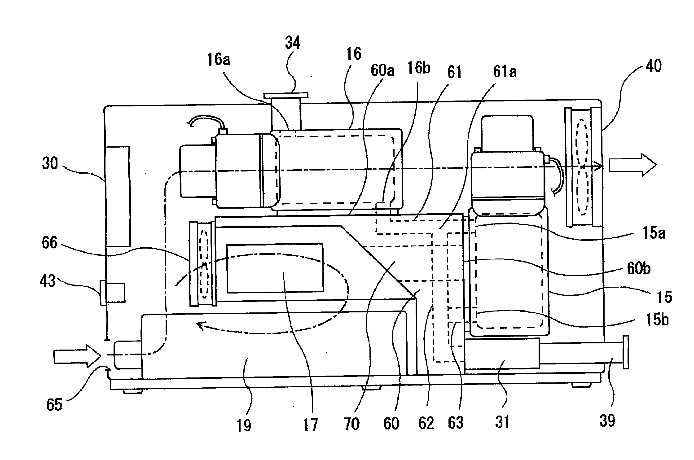
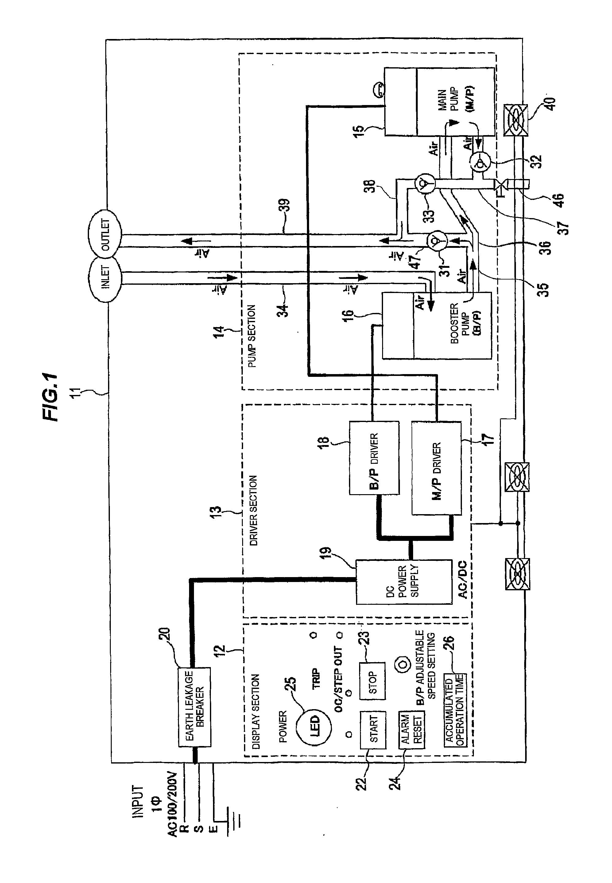
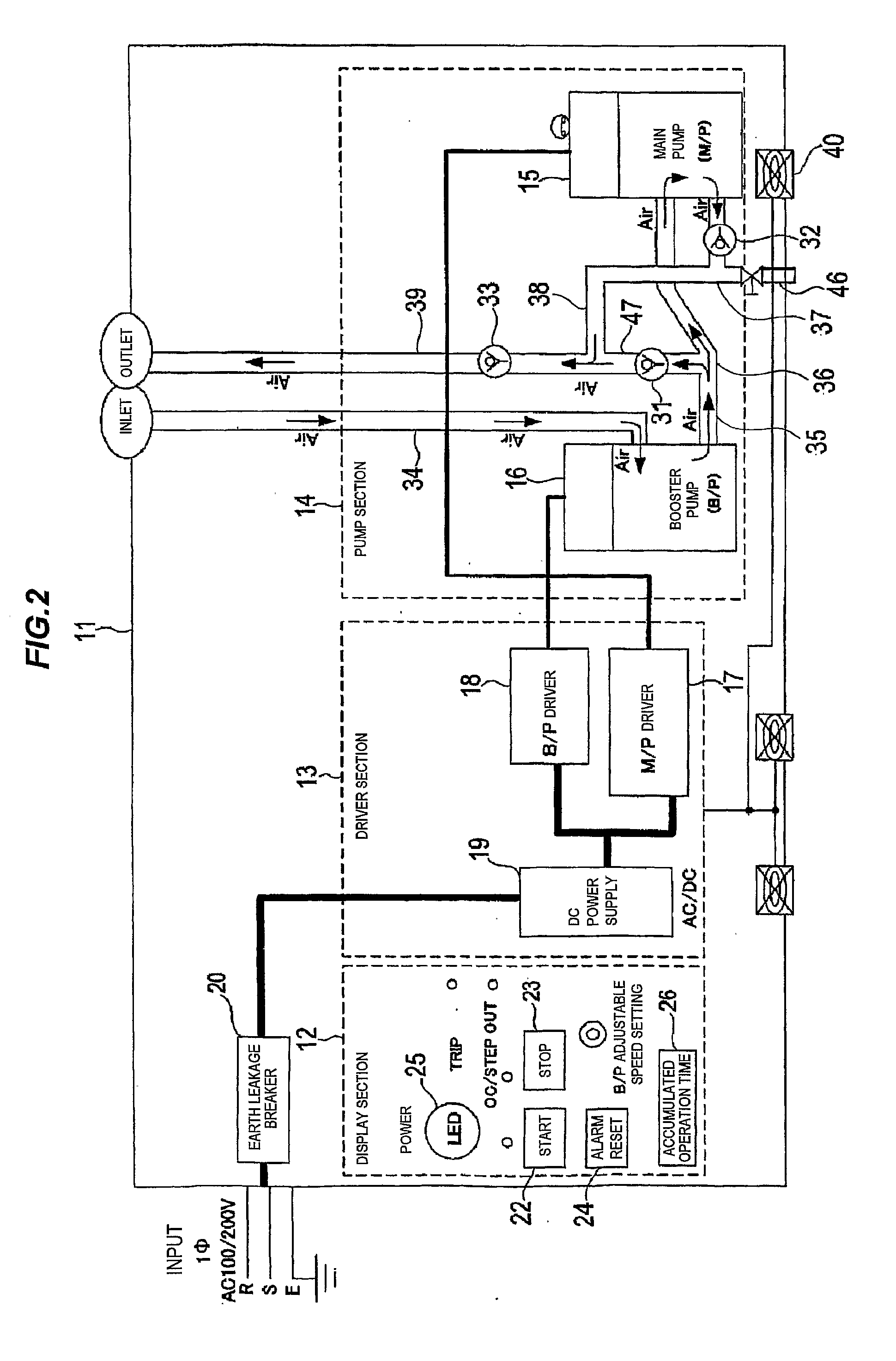
[0053]FIG. 1 is a schematic view showing a vacuum pump unit according to an embodiment of the present invention. FIG. 2 is a view showing a modified arrangement of valves shown in FIG. 1. A vacuum pump unit 11 comprises a display section 12, a driver section 13, and a pump section 14. The pump section 14 includes two pumps, which are a main pump (roughing vacuum pump) 15 and a booster pump 16 coupled in series. These pumps have the same shape, the same size, and the same displacement volume, i.e., the same structure. However, the main pump 15 and the booster pump 16 may have different structures.

[0054]Each of the vacuum pumps 15 and 16 is a two-axis positive displacement screw pump which has no timing gears, but uses non-contact magnet coupling that provides sy...


PUM


Abstract

The present invention relates to a dry vacuum pump unit capable of achieving ultimate pressure of about 1 Pa. The vacuum pump unit includes a main pump (15) disposed at an outside-pressure side, and a booster pump (16) disposed at a vacuum side. The booster pump (16) and the main pump (15) are coupled in series. The booster pump (16) has a higher pumping speed than that of the main pump (15). Each of the main pump (15) and the booster pump (16) includes a pair of pump rotors (52a and 52b), a casing (50) having an inlet port and an outlet port, and a pair of magnet rotors (54 and 54) rotatable with the pair of pump rotors.

Description

TECHNICAL FIELD[0001]The present invention relates to a dry vacuum pump unit capable of achieving ultimate pressure of about 1 Pa.BACKGROUND ART[0002]A vacuum pump having the above-described pumping performance is used in a sputtering apparatus, a helium leak detector, an analyzer (e.g., SEM), and the like. Further, the vacuum pump having the above-described pumping performance is used as a roughing vacuum pump coupled to a high-vacuum pump, such as a turbo molecular pump, and is also used in a vacuum dryer or a vacuum bonding apparatus that sucks a gas, e.g., water vapor.[0003]An oil-sealed rotary pump is typically used as a small-volume vacuum pump which is small size, portable, and inexpensive. However, this type of pump presents several problems including back diffusion of oil vapor into a vacuum chamber (contamination of the vacuum chamber and a workpiece), oil contamination of discharge lines (fire hazard), environmental pollution, a decrease in oil due to the oil diffusion, d...

Claims


Application Information

Patent Timeline
Patent Type & Authority Applications(United States)
IPC IPC(8): F04B25/00F16M5/00
CPCF04C18/16F04C23/00F04C23/001H02K16/00F04C28/24F04C29/0085H02K7/11F04C25/02F04C28/02
Inventor HOZUMI, TAKASHIMIYASHITA, NOBUHITOINADA, TAKANORIMATAKE, KOZOOJIMA, YOSHINORIMIYAKE, SUSUMUUSUI, KATSUAKI
Owner EBARA CORP
Why Eureka
Try Eureka