Engine Start Device

Inactive Publication Date: 2009-02-26
PANASONIC CORP
View PDF12 Cites 34 Cited by
  • Summary
  • Abstract
  • Description
  • Claims
  • Application Information

AI Technical Summary

Benefits of technology

[0013]According to the engine start device of the present invention, a total amount of the voltage of the battery and the charge voltage of the electric double layer capacitor is applied to the starter. With the application of voltage higher than that obtained by the battery voltage only,

Problems solved by technology

In addition, the device can cope with decrease in battery

Method used


Image

  • Engine Start Device
  • Engine Start Device
  • Engine Start Device

Examples


first exemplary embodiment

[0034]Hereinafter, the structure of the first exemplary embodiment will be described with reference to FIG. 1 through FIG. 5.

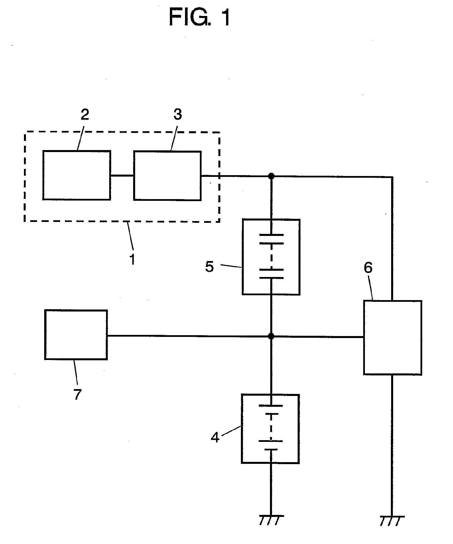
[0035]FIG. 1 is a circuit diagram showing the structure of an engine start device in accordance with the first exemplary embodiment of the present invention. Starter 1 in FIG. 1, which is connected to the driving system of the engine, is formed of starter motor 2 and starter relay 3. Generator 7 is connected to the driving system of the engine. Battery 4 is a lead acid battery with a voltage rating of 12V. Electric double layer capacitor 5 is connected between starter 1 and battery 4. An input terminal of DC / DC converter 6 is connected to the junction point of generator 7 and battery 4 and an output terminal of converter 6 is connected to the junction point of starter 1 and electric double layer capacitor 5.

[0036]How to start the engine in the engine start device structured above is described hereinafter.

[0037]Prior to the initial start of the engine, receivin...

second exemplary embodiment

[0066]Hereinafter, the structure of the second exemplary embodiment will be described with reference to FIG. 6 and FIG. 7.

[0067]FIG. 6 is a circuit diagram showing the structure of an engine start device in accordance with the second exemplary embodiment of the present invention. In FIG. 6, like parts are identified by the same reference numerals as in FIG. 1 and the explanation thereof will be omitted.

[0068]As is shown in FIG. 6, diode 10 is connected in parallel to electric double layer capacitor 5. The cathode of diode 10 is connected to the positive pole of electric double layer capacitor 5.

[0069]Now will be described the engine start operation of the engine start device having the structure above.

[0070]In the initial start of the engine, that is, under the condition where electric double layer capacitor 5 has no charge or lack of charge, when starter relay 3 is turned ON, the voltage of battery 4 is applied to starter motor 2 via diode 10, so that electric current is fed to sta...

third exemplary embodiment

[0081]Hereinafter, the structure of the third exemplary embodiment will be described with reference to FIG. 8 and FIG. 9.

[0082]The structure of the embodiment differs from those of the first and the second embodiments in that the DC / DC converter has a two-way structure. In the structure of the embodiment, like parts are identified by the same reference numerals as in the structures described in the previous two embodiments and the explanation hereinafter will be focused on the difference.

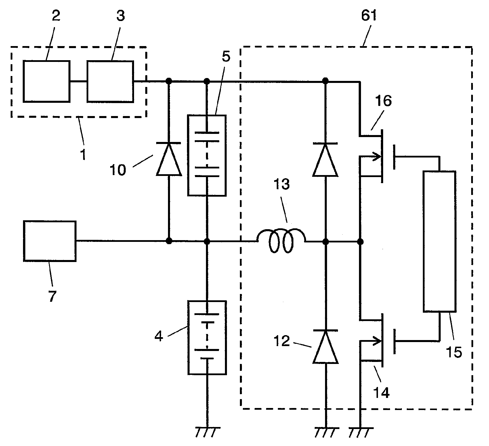
[0083]FIG. 8 is a circuit diagram showing the structure of an engine start device in accordance with the third exemplary embodiment of the present invention. DC / DC converter 61 having a two-way circuit structure also improves the performance of the engine in start-up operation.

[0084]Now will be described the effect brought by two-way DC / DC converter 61.

[0085]FIG. 8 shows an inverting chopper circuit driven on a synchronous rectification system as an example of a two-way converter. Switching element ...


PUM


Abstract

An engine start device includes a generator, a battery charged by the generator, a starter, an electric double layer capacitor and a DC/DC converter. The electric double layer capacitor is connected between the starter and the battery. The DC/DC converter has an input terminal connected to the battery and the electric double layer capacitor. The DC/DC converter has an output terminal connected to the starter and the electric double layer capacitor. According to voltage of the battery, internal DC resistance of the battery or internal DC resistance of the electric double layer capacitor, the DC/DC converter effects control of charge voltage of the electric double layer capacitor so as to stabilize voltage applied to a starter motor and stabilize the engine start.

Description

TECHNICAL FIELD[0001]The present invention relates to an engine start device that supplies power to a starter connected to a driving system of an engine; specifically, relates to a stop-idling operation in a vehicle employing a single battery, i.e., an ordinary vehicle driven on 14V system.BACKGROUND ART[0002]In recent years, from the viewpoint of environmental protection, the motor vehicle industry has promoted technological innovation, as is seen in a hybrid car that has been in practical use. Besides, an advanced vehicle having a stop-idling function—the engine temporarily makes a stop under a certain condition and automatically restarts—has been already on the market.[0003]Vehicles with a stop-idling function operate on various driving systems: a 14V system and a 42V system. The 14V system employs a single battery with a voltage rating of 12V, whereas the 42V system employs a combined use of a battery with a voltage rating of 36V and a battery with a voltage rating of 12V. Compa...

Claims


Application Information

Patent Timeline
IPC IPC(8): F02N11/04
CPCF02N11/04F02N11/0866F02N2011/0885H02P1/18F02N2200/063H02J7/345F02N2011/0888
Inventor HANDA, HIROYUKIYOSHIDA, KOJI
Owner PANASONIC CORP
Why Eureka
Try Eureka