Stress-Stimulated Luminescent Material, Manufacturing Method Thereof, Composite Material Including the Stress-Stimulated Luminescent Material, and Base Material Structure of the Stress-Stimulated Luminescent Material

a luminescent material and stress-stimulated technology, which is applied in the direction of luminescent compositions, lighting and heating apparatus, and can solve the problems of insufficient luminescence intensity of conventional stress-stimulated luminescent materials, and achieve high luminescence intensity, broadening the use and application of stress-stimulated luminescent materials.

Inactive Publication Date: 2009-02-26
NAT INST OF ADVANCED IND SCI & TECH
View PDF5 Cites 65 Cited by
  • Summary
  • Abstract
  • Description
  • Claims
  • Application Information

AI Technical Summary

Benefits of technology

[0032]As described above, the luminescent material according to the present invention comprising a basic structure in which a plurality of molecules each having at least an AlO4-like tetrahedral structure or an SiO4-like tetrahedral structure share atoms of apexes of the tetrahedral structures so as to be coupled to one another so that a basic material structure is formed and at least either alkali metal ions or alkali earth metal ions are inserted into a void of the base material structure, wherein the base material structure has an asymmetric framework structure, and at least either the alkali metal ions or the alkali earth metal ions inserted into the void are partially substituted by at least either rare earth metal ions or transition metal ions. That is, the stress-stimulated luminescent material includes the base material structure for exhibiting high luminescence intensity in response to a stress. The base material structure of the stress-stimulated luminescent material has a void which is likely to strain the base material structure, so that it is possible to realize high luminescence intensity which cannot be achieved by the conventional art, thereby broadening a usage and application of the stress-stimulated luminescent material.

Problems solved by technology

However, luminescence intensity of the conventional stress-stimulated luminescent material may be insufficient.

Method used


Image

  • Stress-Stimulated Luminescent Material, Manufacturing Method Thereof, Composite Material Including the Stress-Stimulated Luminescent Material, and Base Material Structure of the Stress-Stimulated Luminescent Material
  • Stress-Stimulated Luminescent Material, Manufacturing Method Thereof, Composite Material Including the Stress-Stimulated Luminescent Material, and Base Material Structure of the Stress-Stimulated Luminescent Material
  • Stress-Stimulated Luminescent Material, Manufacturing Method Thereof, Composite Material Including the Stress-Stimulated Luminescent Material, and Base Material Structure of the Stress-Stimulated Luminescent Material

Examples


example

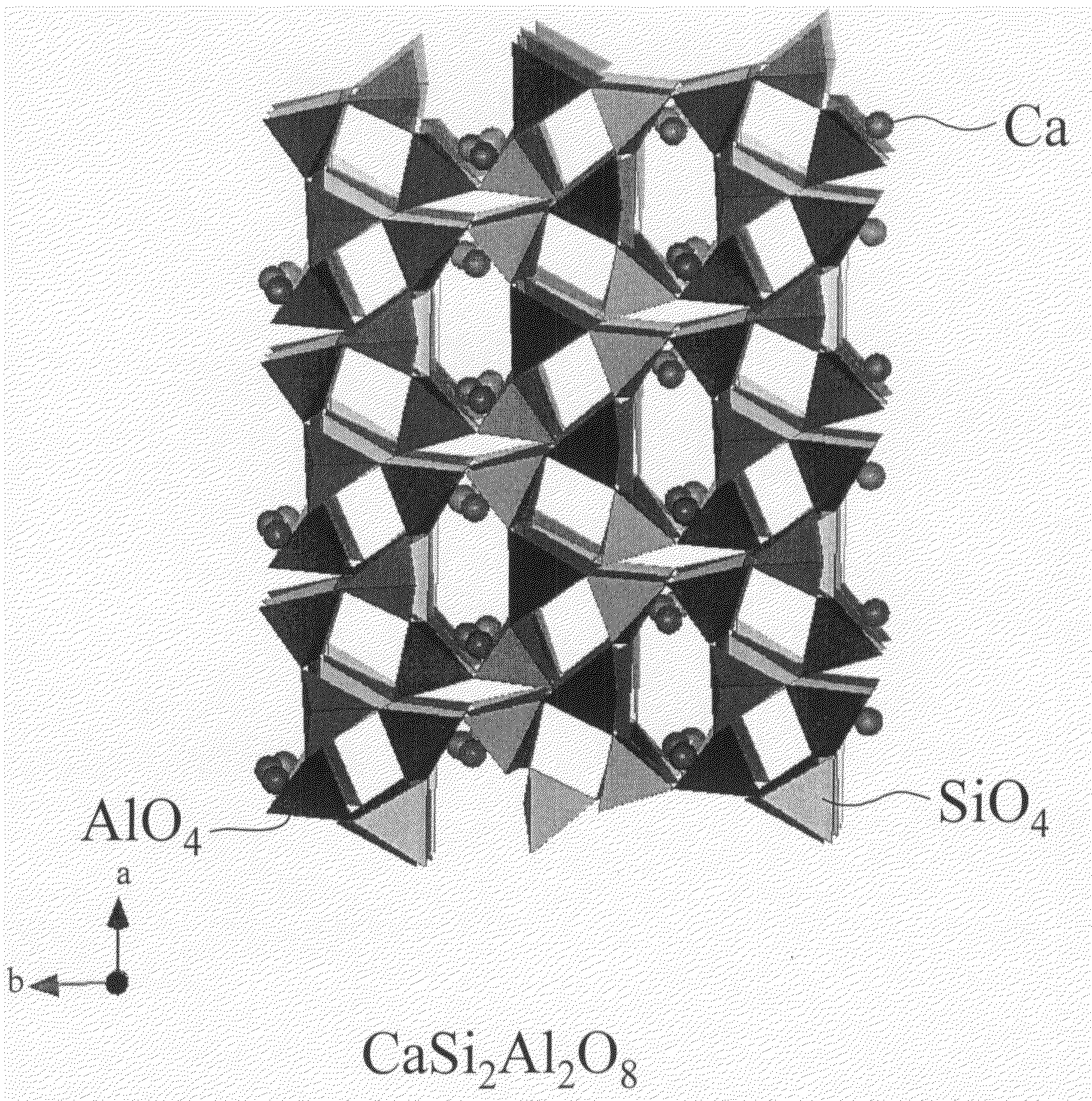
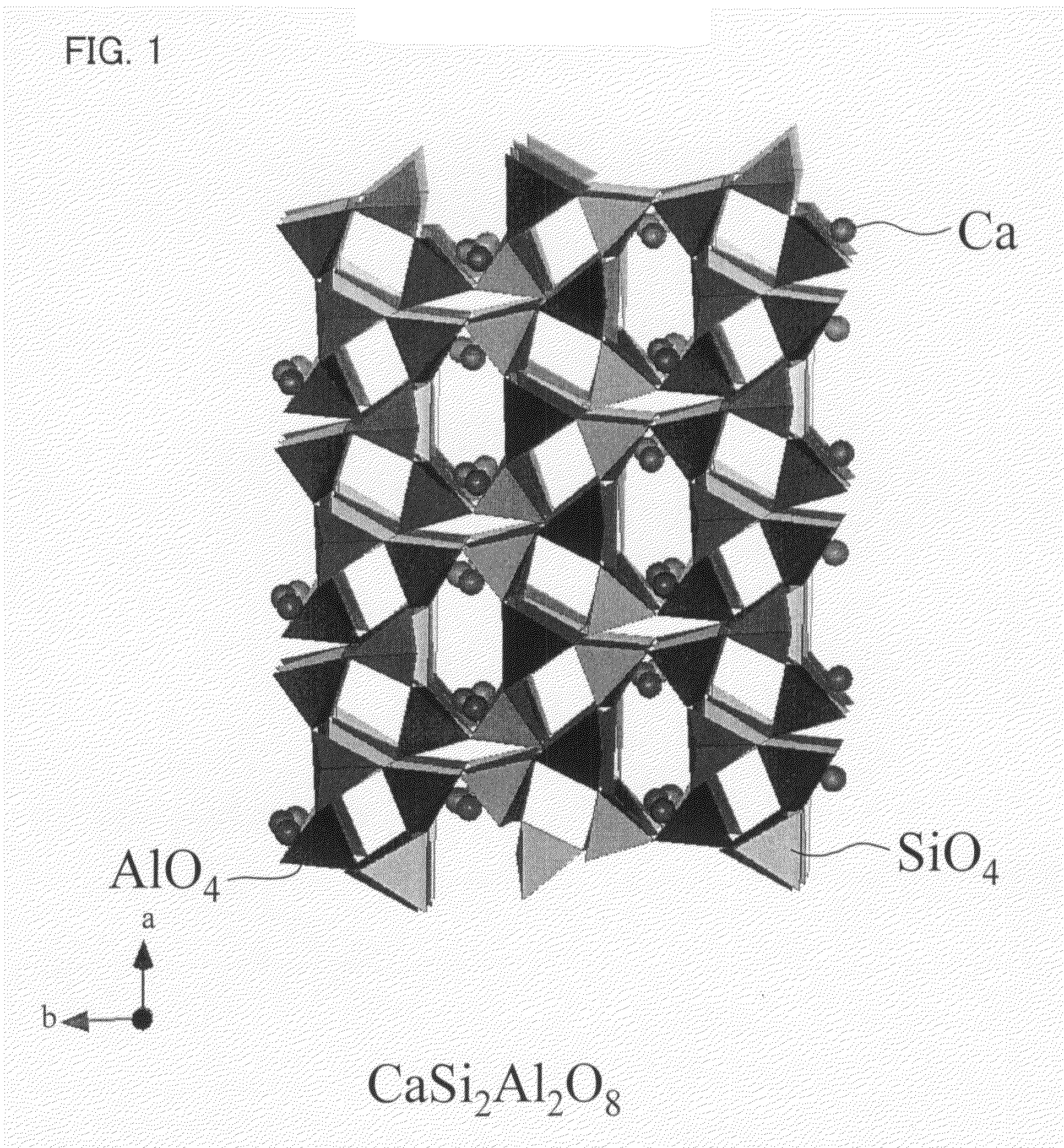
[0113]The following Example describes a case of using Ca as alkali earth metal and using AlO4 and SiO4 as polyhedrons of the base material structure (three-dimensional framework).

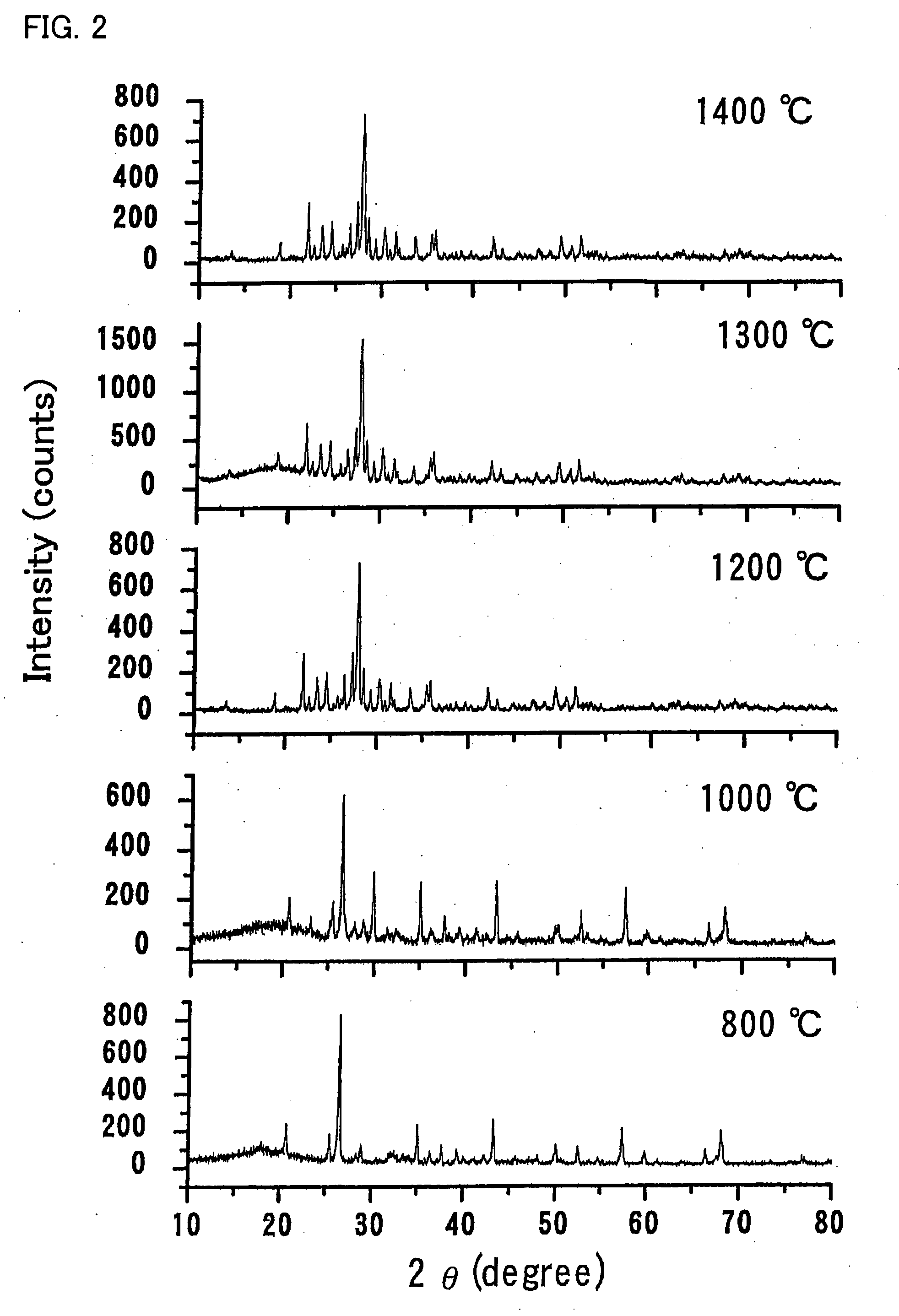
[0114]Predetermined amounts of calcium carbonate CaCO3, aluminum oxide Al2O3, Eu2O3, Dy2O3, and silicon dioxide SiO2 were weighed so that a composition of Ca1−x−yEuxDyyAl2Si2O8 (x=0.01 and y=0.005) was realized. Subsequently, the weighed materials were sufficiently mixed in an ethanol with a ball mill, and then the mixture was dried at 80° C. The heated mixture was crushed in a triturator, and then the crushed mixture was sintered at 1400° C. for four hours in a reduction atmosphere (5% hydrogen-containing argon). Note that, the temperature was slowly raised or dropped by 2° C. per minute. Next, the resultant material after the sintering was pulverized, thereby preparing powder of a stress-stimulated luminescent material. Further, the powdery sample was subjected to X-ray diffraction (XRD) measurement, ultr...


PUM

PropertyMeasurementUnit
stressaaaaaaaaaa
ion radiusaaaaaaaaaa
luminescentaaaaaaaaaa

Abstract

One embodiment of the present invention is to provide a stress-stimulated luminescent material which has a unique crystal structure and which emits conventionally unachievable intense light. The stress-stimulated luminescent material of one embodiment of the present invention includes a basic structure in which a plurality of tetrahedral molecules each having an AlO4-like tetrahedral structure or an SiO4-like tetrahedral structure share atoms of apexes of the tetrahedral structures so as to be coupled to one another so that a basic material structure is formed and at least either alkali metal ions or alkali earth metal ions are inserted into the void are partially substituted by at least either rare earth metal ions or transition metal ions.

Description

TECHNICAL FIELD[0001]The present invention relates to (i) a stress-stimulated luminescent material which emits particularly intense light in response to a mechanical stress, (ii) a manufacturing method thereof, (iii) a composite material having the stress-stimulated luminescent material, and (iv) a base material structure of the stress-stimulated luminescent material.BACKGROUND ART[0002]Conventionally, such a phenomenon that visible light is emitted in response to various stimuli from the outside (external stimuli) has been known (such phenomenon is so-called “fluorescent phenomenon”). A material exhibiting the fluorescent phenomenon is referred to as a fluorescent material, and is used in various fields such as a lamp or a panel light, various types of displays such as a cathode ray tube or a plasma display panel, pigments, and the like.[0003]Further, a large number of materials exhibiting the fluorescent phenomenon in response to external stimuli such as an ultraviolet ray, an ele...

Claims


Application Information

Patent Timeline
Patent Type & Authority Applications(United States)
IPC IPC(8): C09K11/08
CPCC09K11/7706C09K11/7734F21K2/04C09K11/7792C09K11/7774C09K11/77064C09K11/77344C09K11/77924C09K11/77744
Inventor XU, CHAO-NANYAMADA, HIROSHI
Owner NAT INST OF ADVANCED IND SCI & TECH
Why Eureka
Try Eureka