
Selective wet etching of gold-tin based solder

a wet etching and gold-tin technology, applied in the field of semiconductor/solid-state device manufacturing, semiconductor devices, electrical equipment, etc., can solve the problems of voids in materials, and poor wet etching effect of solder paste,

Active Publication Date: 2009-02-26
CREE INC
View PDF45 Cites 4 Cited by
  • Summary
  • Abstract
  • Description
  • Claims
  • Application Information

AI Technical Summary

Benefits of technology

[0014]The present invention provides improved methods for fabricating devices, particularly methods for patterning one or more materials in light emitting devices. These methods use one or more standard available chemistries to wet etch AuSn solder material, thereby circumventing the need for, and limitations of, selective AuSn deposition processes.
[0016]In particular, the present invention utilizes a combination of wet chemistries to selectively etch an AuSn solder layer deposited on a substrate or other areas or layers of a semiconductor device, either before or after the layer is reflowed at the eutectic point. Multiple etching steps that alternate between different mixes of chemicals enables the etch to proceed effectively, and the same or similar processes can be used to etch under bump metallization (e.g. Ti, Ni, Pt, Au).

Problems solved by technology

These technologies, however, suffer from certain disadvantages.
Due to incorporation of flux in the solder paste, screen-printing of solder paste is not a clean process.
The paste typically undergoes reflow to drive off the flux, which can lead to contamination and leave voids in the material.
However, the technology is thickness and size-limited, and also costly due to the need to physically place preform on a wafer.
In practice, therefore, the use of selective area deposition restricts the range of device architectures that are possible for AuSn solder due to the inherent limitations of available deposition techniques.
Additionally, in some cases it is simply not desirable to pattern the AuSn at the time it is deposited.

Method used


Image

  • Selective wet etching of gold-tin based solder
  • Selective wet etching of gold-tin based solder
  • Selective wet etching of gold-tin based solder

Examples


example 1

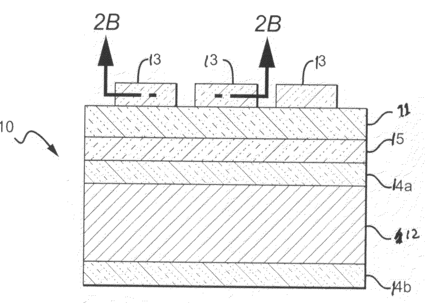
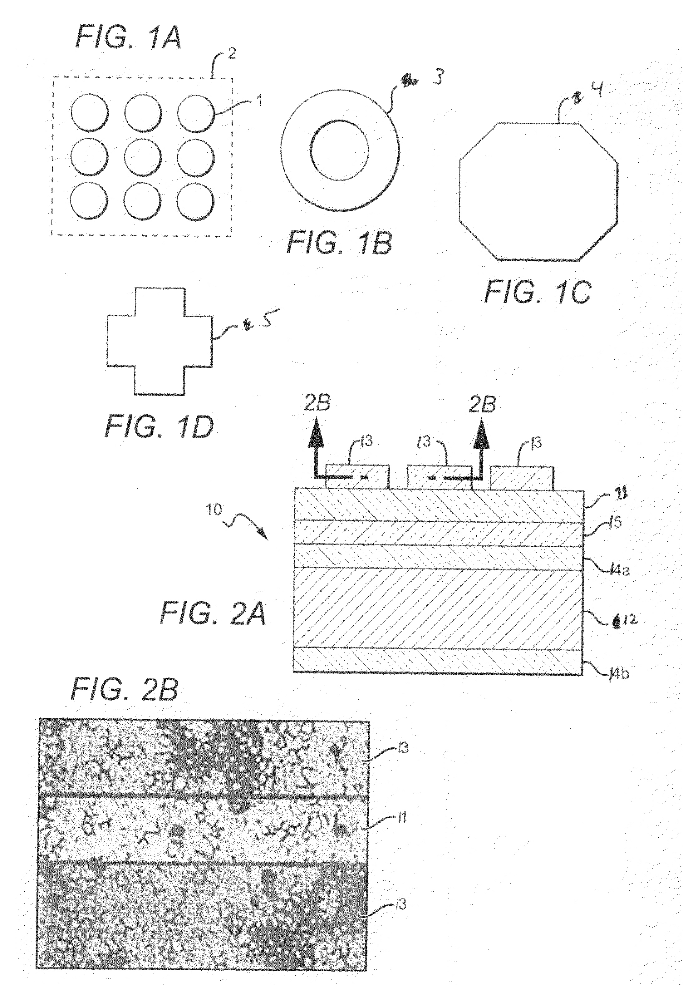
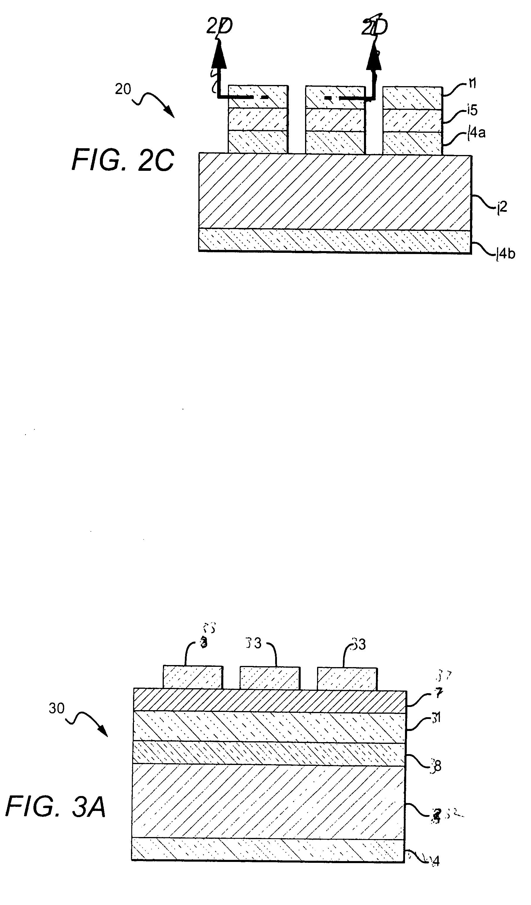
[0056]The following describes one embodiment of a method according to the present invention used to etch a structure having an AuSn feature or layer. The structure being etched comprises an AuSn layer that can be formed from a preform that was reflowed onto a thermally oxidized Si carrier wafer having a Ti / Pt / Au blanket metallization. The AuSn layer can have many different thickness and the Si wafer can have many different diameters, with a suitable AuSn layer being 0.5 millimeters thick and the wafer having a 2 inch diameter. A resist mask layer is included on the AuSn layer with a suitable layer comprising commercially available photoresist 220-7 and being approximately 6 μm thick. A standard quartz plate lithography mask layer (i.e. 220-7 photoresist) followed by a 3 minute post-bake at 110° C.

[0057]Two solutions were then used in an alternating fashion for wet etching, as indicated below:

[0058]1. HF / HCl (1:1)—1 min.

[0059]2. Aqua-regia—1 min.

[0060]3. HF / HCl (1:1)—0.5 min.

[0061]4....

example 2

[0067]Many different etching chemistries can be used according to the present invention and can be applied for different amounts of time. As another example, a metallized Si carrier wafer with a sputter AuSn layer that was not reflowed, was etched. Two different approaches were used for wet etching experiments:

1. HF / HCl (1:1)—1 min

2. Aqua-regia—1 min


PUM


Abstract

The present invention is directed to post-deposition, wet etch processes for patterning AuSn solder material and devices fabricated using such processes. The processes can be applied to uniform AuSn layers to generate submicron patterning of thin AuSn layers having a wide variety of features. The use of multiple etching steps that alternate between different mixes of chemicals enables the etch to proceed effectively, and the same or similar processes can be used to etch under bump metallization. The processes are simple, cost-effective, do not contaminate equipment or tools, and are compatible with standard cleanroom fabrication processes.

Description

STATEMENT AS TO FEDERALLY SPONSORED RESEARCH[0001]This invention was made with Government support under Grant No. 70NANB4H3037 awarded by the Department of Commerce (DOC). The federal government may have certain rights in the invention.BACKGROUND OF THE INVENTION[0002]1. Field of the Invention[0003]The present invention relates to semiconductor devices, and more particularly to light emitting devices and methods of fabricating light emitting devices.[0004]2. Description of Related Art[0005]Light emitting diodes and laser diodes are well known solid state electronic devices capable of generating light upon application of a sufficient voltage. Light emitting diodes and laser diodes may be generally referred to as light emitting devices (LEDs). Light emitting devices typically include a p-n junction formed in an epitaxial (epi) layer such as gallium nitride (GaN). The epi layer is usually grown on a substrate such as sapphire (Al2O3), silicon (Si), silicon carbide (SiC), or gallium ars...

Claims


Application Information

Patent Timeline
IPC IPC(8): H01L33/00H01L21/44H01L33/36
CPCH01L33/36H01L33/005C23F1/02C23F1/30C23F1/44
Inventor CHITNIS, ASHAY
Owner CREE INC
Learn More