
Railroad wheel steels having improved resistance to rolling contact fatigue

a technology of rolling contact fatigue and railroad wheels, which is applied in the direction of rail-engaging wheels, transportation and packaging, vehicle components, etc., can solve the problems of steel rail wheels eventually wear out, the thermo-mechanical deterioration of the wheels is often premature, and the thermo-mechanical deterioration is a problem, so as to improve the metallurgical properties

Inactive Publication Date: 2009-02-26
TRANSPORTATION TECH CENT
View PDF15 Cites 12 Cited by
  • Summary
  • Abstract
  • Description
  • Claims
  • Application Information

AI Technical Summary

Benefits of technology

[0031]Steel alloys characterized by their pearlitic microstructures and having the formulations given below can be used to make railway wheels that are particularly resistant to rolling contact fatigue—and hence shelling. It also should be understood that various physical treatments of the steels having the formulations described in this patent disclosure may be employed during a wheel's manufacture in order to improve its metallurgical p

Problems solved by technology

Steel railroad wheels eventually wear out as a result of normal usage.
Such wheels are however often prematurely forced from service as a result of various forms of thermo-mechanical deterioration.
A great deal of the thermo aspect of thermo-mechanical deterioration results from metallurgical transformation of a railroad wheel's tread / flange steel from its original, relatively tough, pearlitic structure to more brittle structures such as austenite, bainite and / or martensite—with attendant loss of the austenite / bainite / martensite materials through spalling.
Again, thermo deterioration is caused by the heat generated by friction when a train's wheels skid during braking operations.
That is to say that brittle steel materials are produced when such frictional heat is sufficient to raise tread / flange temperatures to austenite that is then transformed to bainite, but in most cases martensite.
In any case, the resulting brittle martensite material then tends to crack and fall away from the wheel.
That is to say that rolling contact fatigue can occur even if the tread steel does not experience metallographic changing temperatures.
Rolling contact fatigue is generally caused by diminished shear fatigue strength of the wheel's tread surface steel.
In any case, rolling contact fatigue is related to both the strength of the wheel tread surface and to the load applied to it.
These relatively greater loads lead directly to higher levels of rolling contact fatigue.
The use of hard steels notwithstanding, railroads are experiencing an increasing incidence of shelling type defects in freight car wheels as a result of the greater loads they are currently being called upon to carry.
Driving forces tend to cause cracks in a wheel's flange regions while normal loads tend to cause shelling of the tread.
Moreover, when brake heated wheels again cool, residual tensile stresses may remain therein and subsequently serve to open any surface cracks that may be present.
For example, elevated temperatures in a wheel steel serve to reduce its ability to resist mechanical loading owing to the steel's diminished mechanical strength above certain temperatures.
Moreover, the longer a wheel steel experiences elevated temperatures and high levels, the greater the degree of shelling that will result from this time related circumstance.
Unfortunately, to varying degrees, these properties range from being metallurgically antagonistic to being metallurgically incompatible.
Conversely, when a steel is alloyed to be more resistant to thermo-generated deterioration, this usually implies that the steel will be less hard, and hence, inherently less wear resistant.
Such steels are not, however, particularly resistant to thermo-mechanical deterioration.
It should be appreciated however that some of these custom based statements can lead to misunderstandings.
This all goes to say that the wear resistance versus thermo-mechanical resistance problem has a persistent dilemmatic quality that continues to thwart the railroad industry's attempts to extend the useful life of railway wheels.
Heat producing wheel skids on the other hand are relatively unpredictable.
Worse yet, thermo-generated deterioration tends to produce damage that is much more immediate and much more severe in nature.
Thus far, alloying theories have been of somewhat limited value in dealing with the wear resistance vs. thermo-mechanical deterioration dilemma.
For example, even though the constitution of three component steels can theoretically be deduced from ternary phase diagrams, they are often rather difficult to interpret.
Their practical value is also limited by the fact that they only describe equilibrium conditions.
Therefore, since most modern railroad wheel steels are both heat treated during their manufacture and contain more than three alloying components, much more complex graphing methods (e.g., Temperature Time Transformation diagrams) must be employed and interpreted—thus far with varying degrees of success as far as railroad wheel steels are concerned.
Further complexities arise from various heat treatment processes to which these steels are usually exposed.
Unfortunately, however, many martensite transformation conditions produced by the heat generated by heavy braking conditions do not coincide with the martensite transformation conditions that can be avoided in highly controlled manufacturing processes such as those disclosed in the '516 patent.
As far as differences in alloying materials are concerned, Applicants employ niobium while the '516 patent disclosure does not teach their use.
In closing their comments on the prior art, Applicants would say that even though a great deal has been learned about rolling contact fatigue, the fact remains that such fatigue is still responsible for a significant part of the accelerated wear of railway wheels in general, and freight car wheels in particular, through shelling of their tread / flange regions.
Indeed, rolling contact fatigue problems are becoming more and more pronounced as freight cars are increasingly being called upon to carry maximum allowable loads.

Method used


Image

  • Railroad wheel steels having improved resistance to rolling contact fatigue
  • Railroad wheel steels having improved resistance to rolling contact fatigue
  • Railroad wheel steels having improved resistance to rolling contact fatigue

Examples


Embodiment Construction

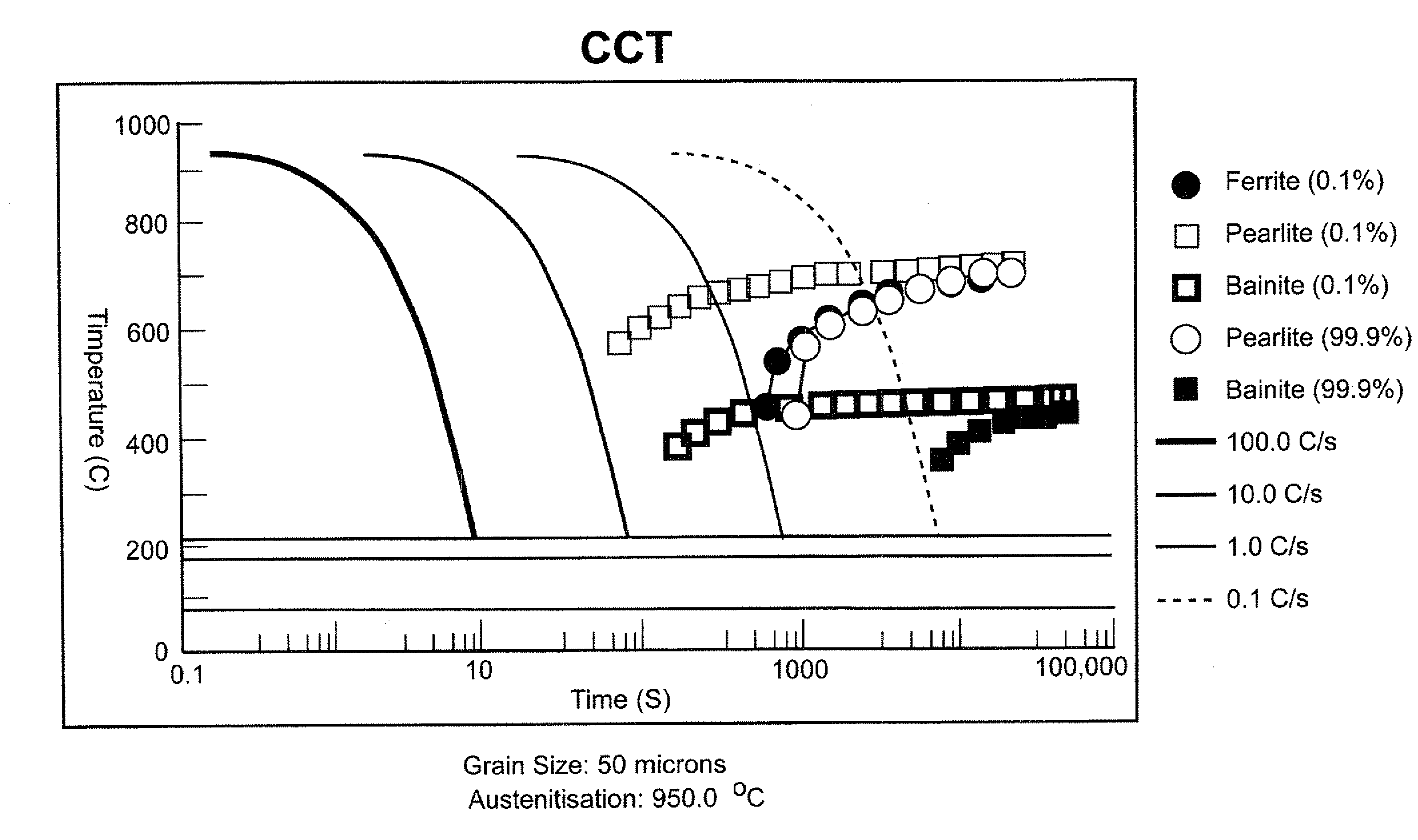
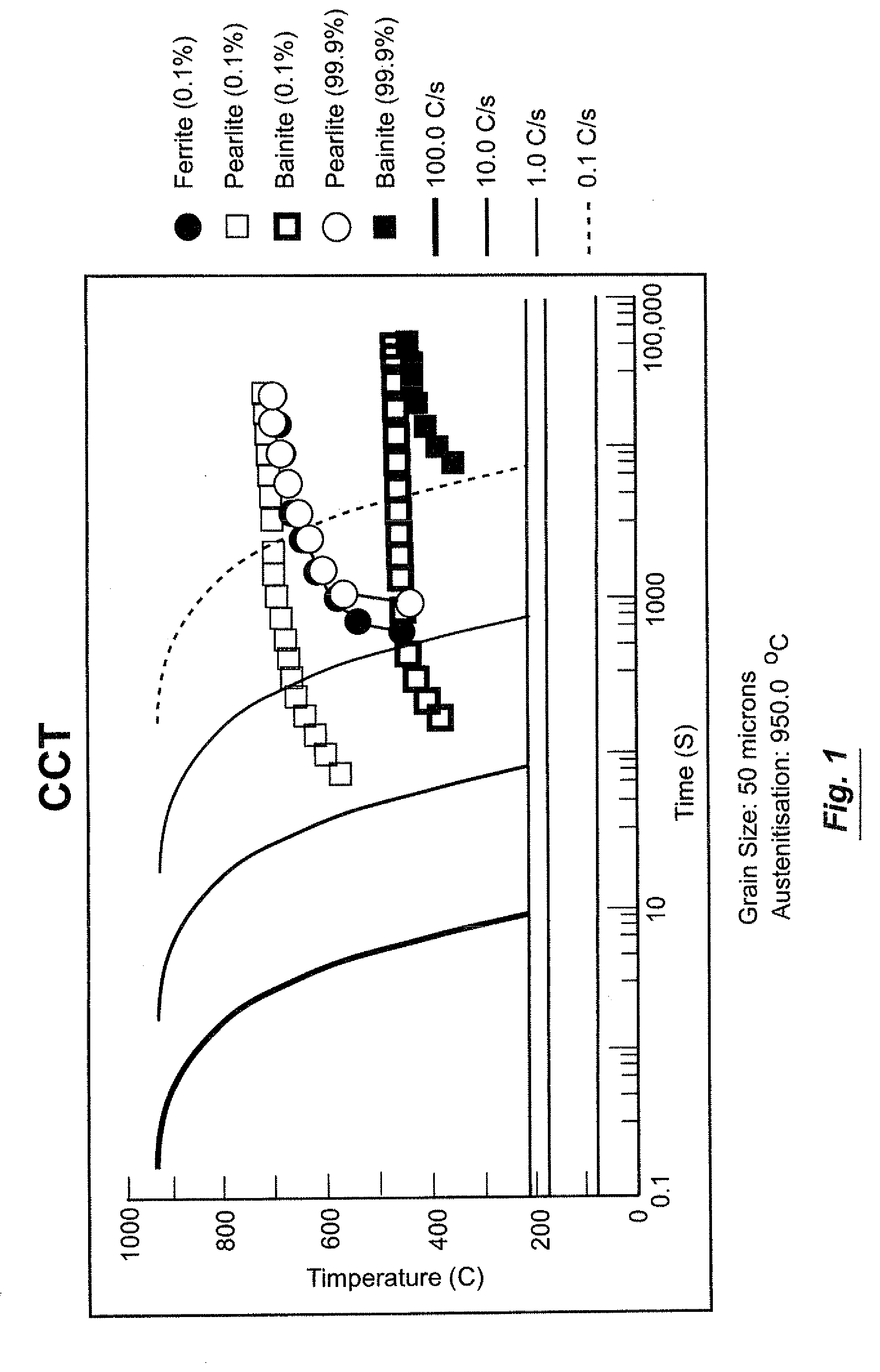
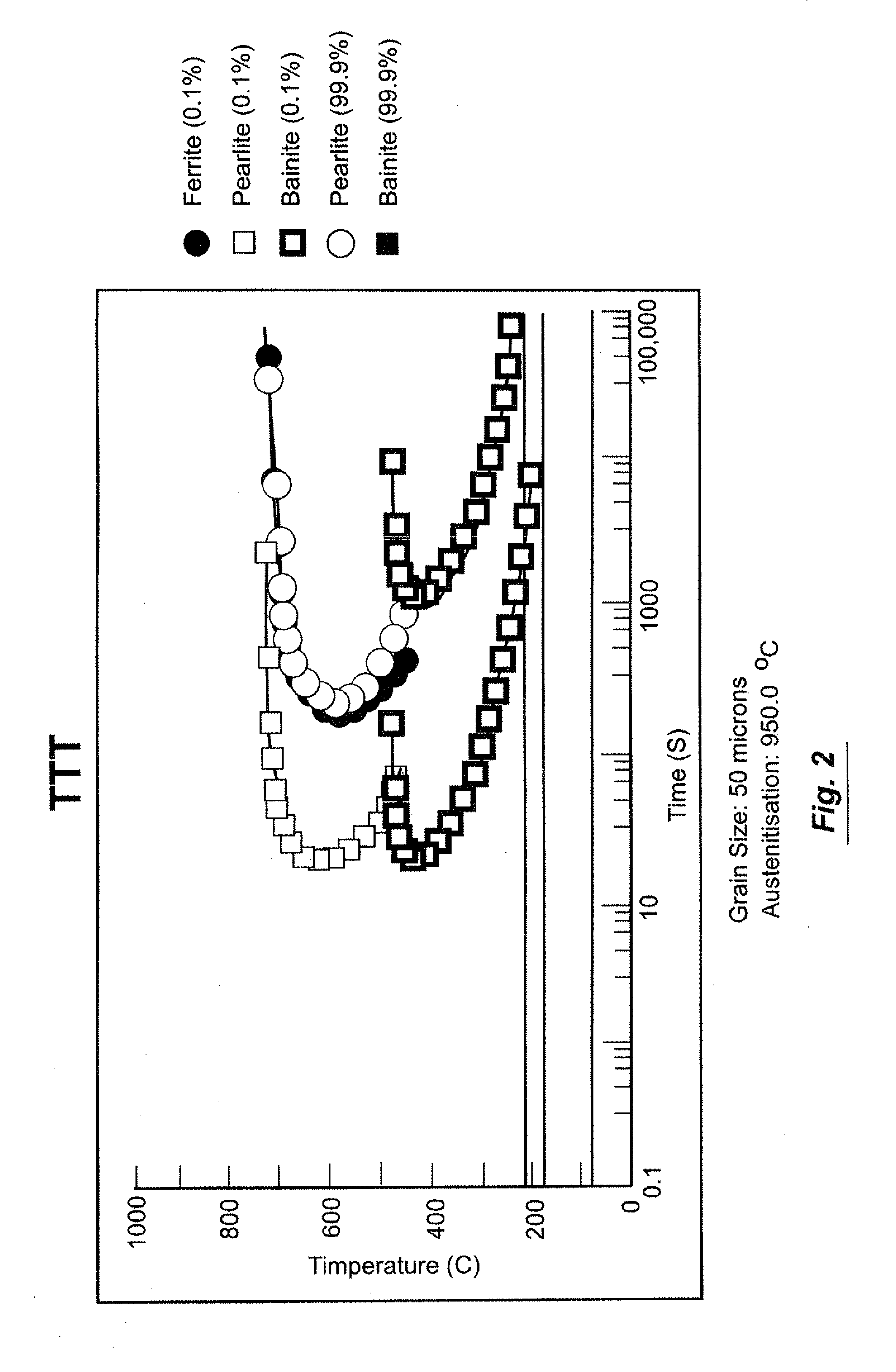
[0050]Applicants have found that the presence of niobium (Nb) in most of the steel formulations of this patent disclosure is usually an especially significant factor in achieving the ends of this invention. That is to say that Applicants have found that niobium is a particularly good grain refiner for these steels and that this grain refinement results in significant improvement in the mechanical properties (e.g., hardness and tensile properties) of these steels. Applicants also have found that the niobium component of these steels acts as a particularly effective austenite stabilizer. This, in turn, serves to prevent formation of a martensite phase—and hence spalling of these steels. Another key point with respect to the presence of niobium in these steels is that a pearlitic transformation of such steels takes place at relatively long austenization times, see for example the continuous cooling transformation (CCT) depicted in FIG. 1 and the temperature time transformation (TTT) de...


PUM

PropertyMeasurementUnit
Strengthaaaaaaaaaa
Brinell hardnessaaaaaaaaaa
Fatigue resistanceaaaaaaaaaa

Abstract

Steels having a pearlitic structure and containing 0.65 to 0.80 weight percent carbon, 0.90 to 1.10 weight percent silicon, 0.85 to 1.15 weight percent manganese, 0.001 to 0.030 weight percent phosphorus, 0.009 to 0.013 weight percent niobium, 0.05 to 0.15 nickel, 0.20 to 0.30 weight percent molybdenum, 0.10 to 0.30 weight percent vanadium and 0.005 to 0.040 weight percent sulfur with the remainder of said steel being iron and incidental impurities, can be used to make railway wheels that are particularly resistant to rolling contact fatigue and, hence, shelling.

Description

BACKGROUND OF THE INVENTION[0001]1. Field of the Invention[0002]The present invention generally relates to railroad wheel steels. More particularly, it is concerned with those railroad wheel steels that are alloyed and / or heat treated to resist both wear and thermo-mechanical deterioration, especially in the tread (and / or flange) regions of such wheels. The terms “spalling” and “shelling” are widely used in describing such thermo-mechanical deterioration. Spalling generally refers to loss of wheel tread material as a result of metallurgical damage created by excessive heat that results from sliding of railroad wheels during train braking operations. Shelling generally refers to loss of wheel tread material as a result of deterioration arising from mechanical stresses.[0003]Various problems arise from each form of tread material loss. By way of example only, thermo-generated deterioration of a railroad wheel's tread can quickly create flat spots on the wheel's outer surface and there...

Claims


Application Information

Patent Timeline
IPC IPC(8): B60B17/02C22C38/12C22C38/22
CPCB60B17/0006C22C38/02C22C38/48C22C38/44C22C38/46C22C38/04
Inventor ROBLES HERNANDEZ, FRANCISCO C.STONE, DANIEL HUNTER
Owner TRANSPORTATION TECH CENT
Learn More