
Remote sensor and in-situ sensor system for improved detection of chemicals in the atmosphere and related method thereof

a technology of in-situ sensor and chemical detection, which is applied in the direction of error detection/correction, chemical methods analysis, instruments, etc., can solve the problems of difficult, or even impossible, to have a single sensor that can meet all these requirements, and achieves low energy, low maintenance, and small size

Inactive Publication Date: 2009-02-26
UNIV OF VIRGINIA ALUMNI PATENTS FOUND
View PDF8 Cites 27 Cited by
  • Summary
  • Abstract
  • Description
  • Claims
  • Application Information

AI Technical Summary

Benefits of technology

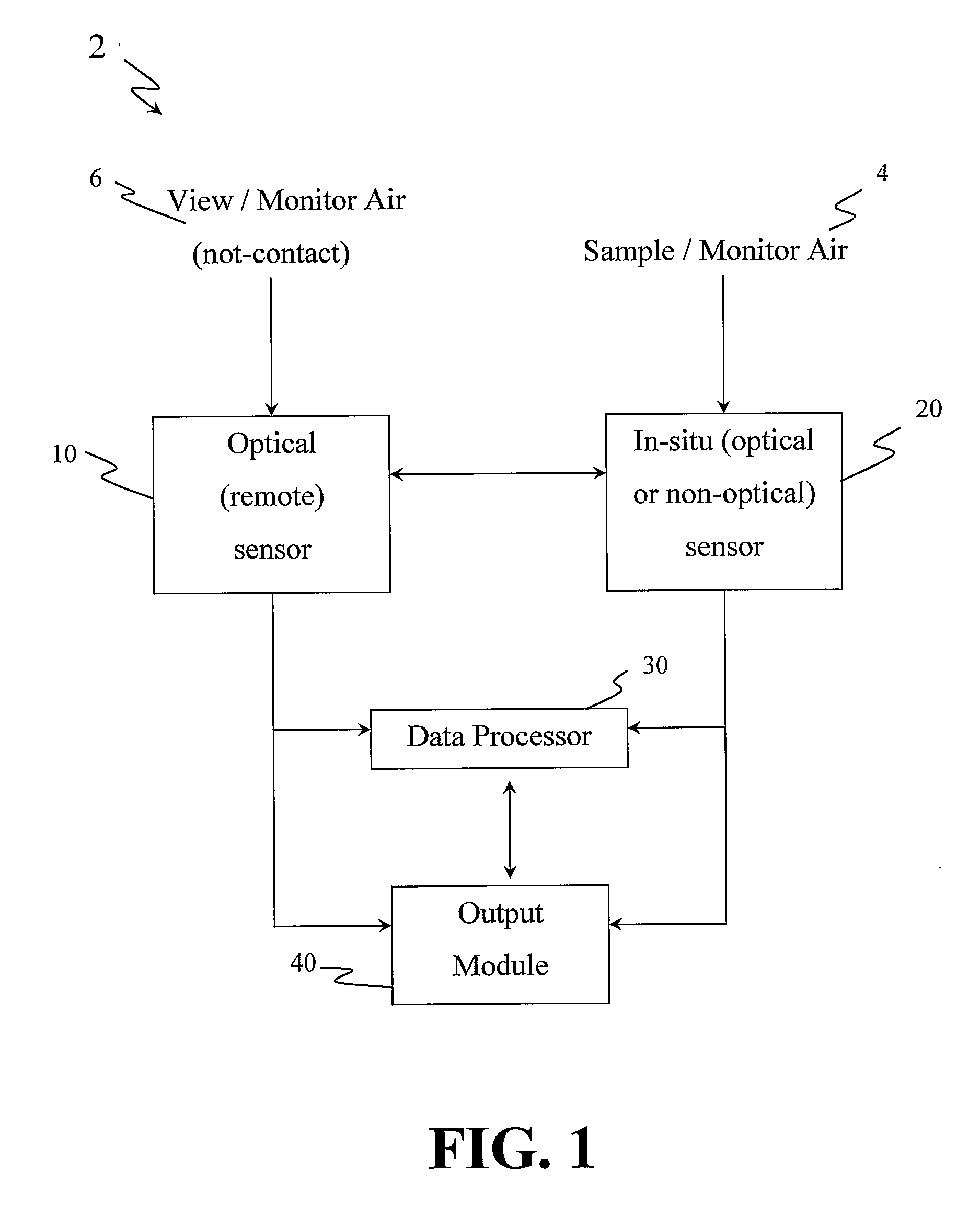
[0003]Some aspects of various embodiments of the present invention provide, but not limited thereto, a system and method for the monitoring of chemicals in the air or atmosphere. Some aspects of various embodiments of the present invention system endeavor to have, but not limited thereto, the following properties: low-cost, low-maintenance, low-false negative and low-false positive thereby implying sensitive and chemical-specific detection, fast, robust, low energy, low maintenance, and of relatively small size. By combining a plurality of sensors operating on independent physical principles, the combined monitoring system can enjoy the advantages of both of its components while overcoming many of their individual disadvantages.
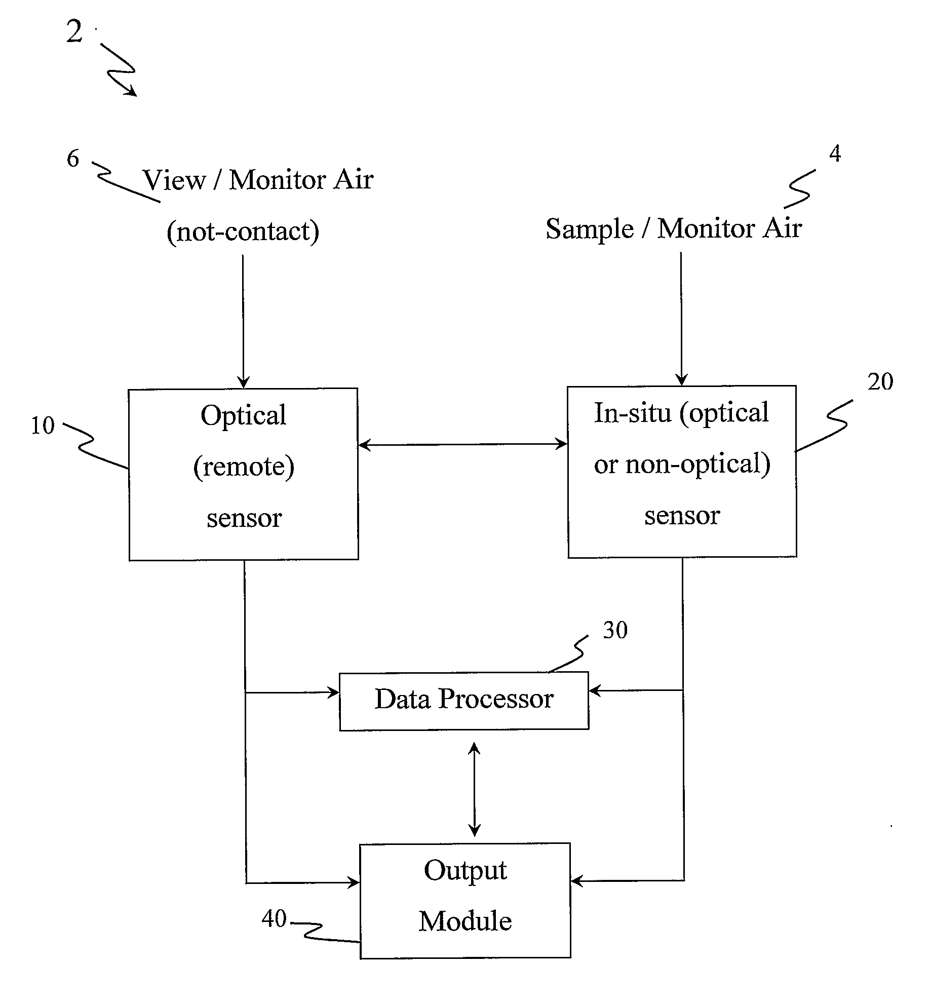
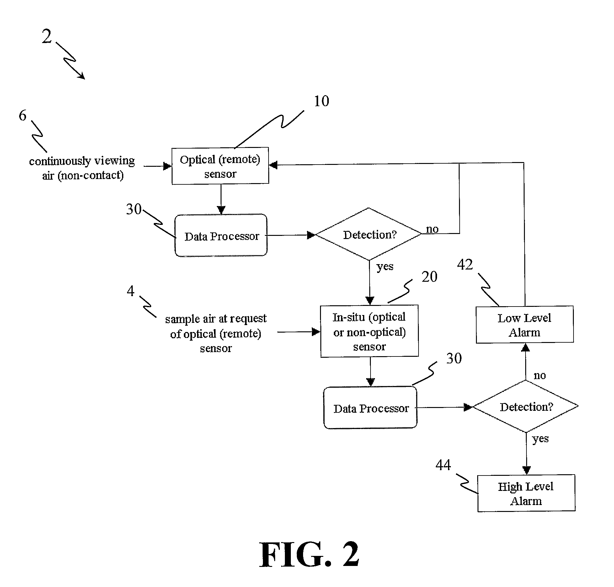
[0004]As an embodiment, for example, by combining an optical remote sensor where sensing can be achieved from distance, and therefore without necessarily making contact with the threat chemical, with one or more in-situ sensors where sampling of air is required, and where at least one sensor is cross-reactive it is possible to achieve, but not limited thereto, the following advantages: (a) by the optical sensor: long range advanced warning, rapid large volume analysis, safety to the operator, (b) by the in-situ sensor: high sensitivity, high specificity, better avoidance of interferences by other, non-target chemicals. For example, when two sensors, each operating on independent physical principles are combined in one monitor, the resulting monitor can be used to provide advanced warning, to map out threat clouds, and then after immersion into the cloud, to reconfirm the threat, to positively identify the chemicals, and to map out the concentration distribution within the cloud. It should be appreciated that depending on the particular arrangement of the various embodiments of the present invention discussed throughout, the remote sensor (optical sensor) is capable of monitoring the same volume or area or partial volume or partial area thereof as monitored by the in-situ monitor. Moreover, it should be appreciated that such monitoring by the remote monitor may be prior to, contemporaneous to, and / or after the monitoring of the in-situ sensor.
[0006]A specific example of the above-stated preferred embodiment would be to combine a multi-spectral radiometer, e.g., the TOTALLY OPTICAL VAPOR ANALYZER (TOVA) with at least one in-situ sensor that uses absorbing polymers for detection such as surface acoustic wave (SAW) devices, micro cantilever (MC) or the ELECTRONIC NOSE (EN). The following U.S. Patents illustrate the EN and the training process and are hereby incorporated by reference herein in their entirety: U.S. Pat. No. 6,319,724 B1 to Lewis et al., entitled “Trace Level Detection of Analytes Using Artificial Olfactometry;” U.S. Pat. No. 5,959,191 to Lewis et al., entitled “Sensor Arrays for Detecting Analytes in Fluids;” U.S. Pat. No. 5,675,070 to Gelperin, entitled “Olfactory Sensor Identification System and Method;” and U.S. Pat. No. 5,571,401 to Lewis et al., entitled “Sensor Arrays for Detecting Analytes in Fluids.” All these sensors can be packaged as low-cost, robust small size sensors. In addition, these sensors may be cross-reactive, i.e., they include multiple channels that have varying sensitivities to the same chemical. Therefore, they can be “trained” to detect a large array of threat and interfering chemicals even after the hardware is built (they can be adjusted to sense new chemicals as the need arises). Furthermore, if both the optical and in-situ sensors have similar output patterns, the processing of the output data can be simplified, thereby reducing costs and accelerating processing time.

Problems solved by technology

It is extremely difficult, or even impossible, to have a single sensor that can meet all these requirements.

Method used


Image

  • Remote sensor and in-situ sensor system for improved detection of chemicals in the atmosphere and related method thereof
  • Remote sensor and in-situ sensor system for improved detection of chemicals in the atmosphere and related method thereof
  • Remote sensor and in-situ sensor system for improved detection of chemicals in the atmosphere and related method thereof

Examples


Embodiment Construction

[0010]There is a need in the art, in part due to the increased threat to homeland security, in particular the threat of terrorist attacks involving toxic chemicals, to provide a monitoring system comprising a plurality of sensors that can detect chemicals in atmosphere (See Joseph R. Biden Jr. “When Chemicals Attack”, The Washington Post, p. A13, Aug. 2, 2005, of which is hereby incorporated by reference herein in it's entirety). Such sensors are also useful for environmental protection, monitoring industrial process, medical facilities, etc. To be effective, such sensors are expected to possess (to varying extents in whole or in part) the following characteristics:[0011]a. provide alarms at high level of confidence (i.e., low rate of false positive and low rate of false negative alarms),[0012]b. be fast, i.e., allow scanning large spaces such as airport terminals within a few seconds, or provide fast alarm to burst of chemical releases within approximately one or two seconds,[0013]...


PUM


Abstract

A system having an optical remote sensor where sensing can be achieved from distance, and therefore without necessarily making contact with the threat chemical, with one or more in-situ sensors where sampling of air is required, and where at least one sensor is cross-reactive. Aspects of some of the various systems capable of achieving, but not limited to thereto, the following advantages: (a) by the optical sensor: long range advanced warning, rapid large volume analysis, fast response continuous monitoring for protection against bursts, safety to the operator, (b) by the in-situ sensor: high sensitivity, (c) by the combination of sensors, high specificity, better avoidance of interferences by chemicals and (d) by the inclusion of cross reactive characteristics, the ability to learn response to new chemicals.

Description

CROSS-REFERENCE TO RELATED APPLICATIONS[0001]The present invention claims priority under 35 U.S.C. Section 119(e) of the earlier filing date of U.S. Provisional Application Ser. No. 60 / 619,259, filed Oct. 15, 2004, entitled “Method and System of Combining an Optical Sensor with In-situ Sensor for Improved Detection of Chemicals in the Atmosphere,” which is hereby incorporated by reference herein in its entirety.BACKGROUND OF THE INVENTION[0002]Protection of domestic facilities such as office buildings or airports and military targets such as airfields, ships or bases requires reliable detection of threat or polluting chemicals in the air. Such sensors should provide alarms for early warning and therefore must be able to operate continuously, have a fast response, high specificity and sensitivity. In addition, after the detection of a release such sensors should provide capabilities for mapping out the spread of such chemicals as means of predicting down-wind hazards and for planning...

Claims


Application Information

Patent Timeline
IPC IPC(8): G01N31/00G06F15/00
CPCG01N1/2273G01N21/3504G01N2001/022G01N2021/394G01N2021/1795G01N2021/3513G01N2021/1734
Inventor LAUFER, GABRIELHOLLAND, STEPHEN KEITHKRAUSS, ROLAND H.
Owner UNIV OF VIRGINIA ALUMNI PATENTS FOUND
Learn More