[0005]The invention has the object to further develop a laser system of the aforementioned kind such that its
operational safety is improved.
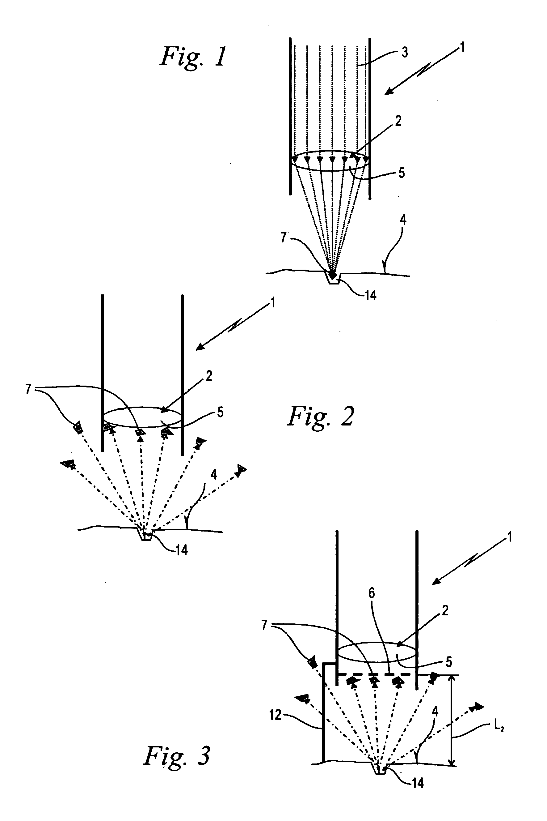
[0008]The protective screen is comprised of structural elements that delimit screen openings. In a preferred embodiment, these structural elements, at least at their surface, are electrically conducting and are connected to an
electric potential, in particular, in the form of electric ground. In this way, the effect is utilized that the particles ejected by the laser beam are electrically charged or even ionized by interaction with the impinging laser beam. At least a significant portion of the ejected particles therefore is exposed by the
electric potential of the protective screen to sufficiently high electrostatic attractive forces in order to be guided toward the structural elements. They
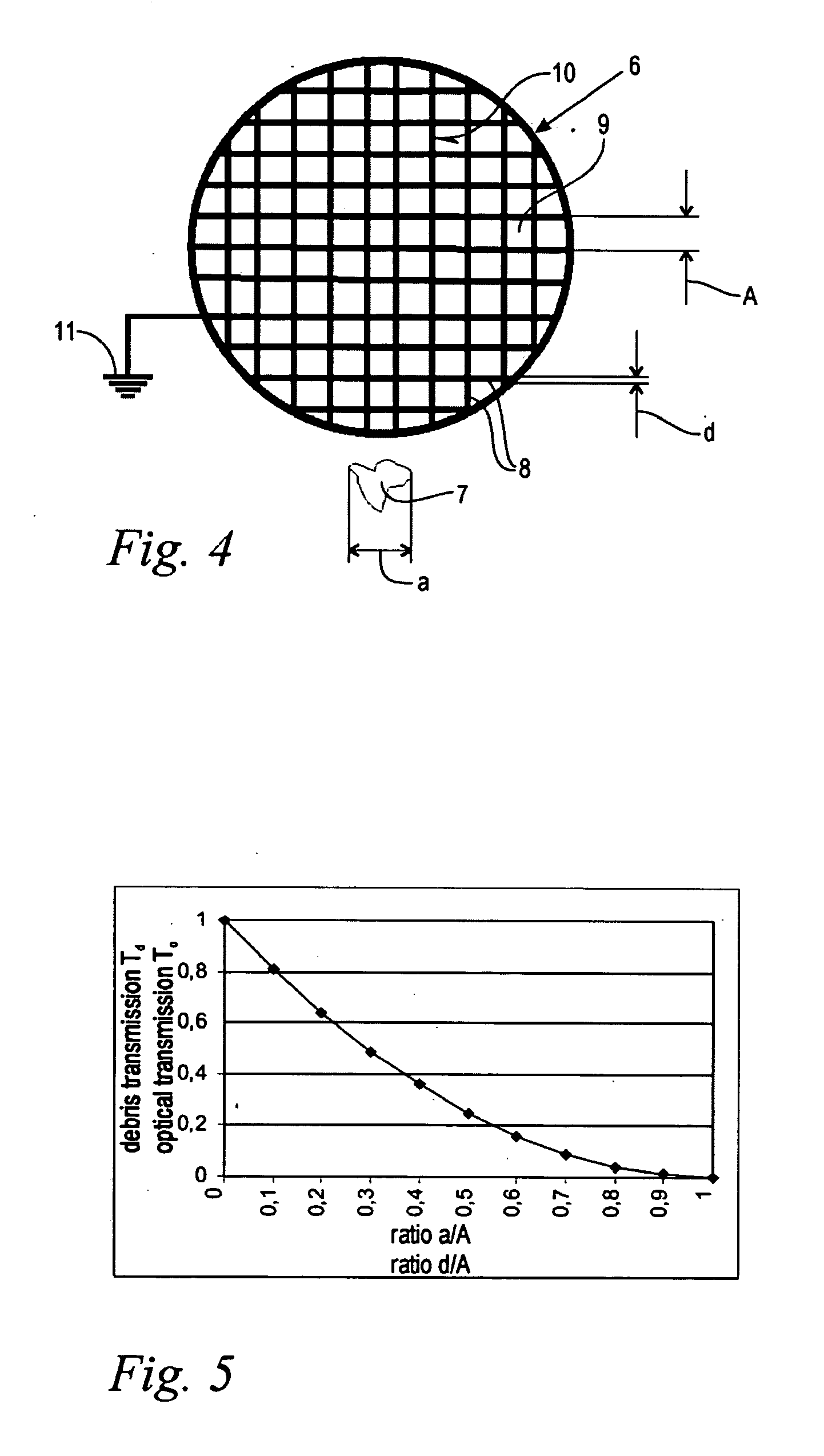
impact on the structural elements and are lodged thereon until they are burnt off by the introduced laser beam. In this way, the external optical element can be shielded even from such particles whose particle size is smaller than the width of the screen openings. A comparatively large-mesh protective screen can be used that has a high optical transmission but still a minimal particle or debris transmission.
[0009]It can be expedient to make only the surface of the structural elements of the protective screen to be electrically conducting. This can be realized, for example, by metallic
vapour deposition on a
ceramic screen structure. In an expedient embodiment, the structural elements of the protective screen are made from
metal and, in particular, from
metal wire. In addition to high electrical
conductivity, this provides also high
thermal load capacity. The wire can be easily made into the desired screen configuration as a welded or soldered arrangement or as a
woven fabric.
[0010]The structural elements of the protective screen are advantageously in the form of, in particular, a square rectangular grid. In this way, a constructively predetermined screen width can be precisely and reproducibly adjusted with minimal expenditure.
[0011]The surface of the structural elements of the protective screen is preferably optically highly reflective. This can be realized, for example, by uncoated, metallic bright non-corrosive
metal surfaces, for example, made from stainless steel or particularly by means of
metallizing the surface. In this way, the
thermal load of the protective screen as a result of
laser beams impinging on the structural elements is reduced.
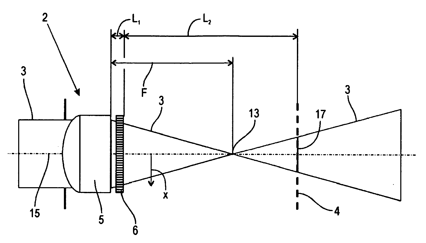
[0013]In a preferred embodiment, the laser system comprises spacer means for maintaining the spacing of the protective screen relative to the target surface. By means of the spacer means, depending on the application, the spacing of the protective screen relative to the target surface can be adjusted to be smaller or greater than the
focal length or even identical to the
focal length of the optical delivery system. In this way, it is possible to vary the intensity of the individual grid-like laser dots on the target surface. In particular, the
maximum intensity of individual laser dots can be increased up to a factor of two and even of three compared to a
laser illumination without protective screen. When the focal point is positioned at least approximately in the target plane, the protective screen does not create a dot pattern of the laser beam on the target plane. Instead, the approximate same intensity distribution is generated on the target surface as in an arrangement without protective screen. The protective screen therefore functions only as a protection means in this situation. As a whole, several adjusting possibilities for different applications are available.

