Composite thermal interface material including aligned nanofiber with low melting temperature binder

a technology of thermal interface materials and carbon nanotube films, which is applied in the field of thermal interface materials, can solve the problem that the materials in such a composite binder necessarily melt, and achieve the effect of enhancing thermal conductivity

Active Publication Date: 2009-03-12
THE BOARD OF TRUSTEES OF THE LELAND STANFORD JUNIOR UNIV
View PDF10 Cites 131 Cited by
  • Summary
  • Abstract
  • Description
  • Claims
  • Application Information

AI Technical Summary

Benefits of technology

[0007]According to one aspect of the invention, a thermal interface material is provided. The material includes a mechanically compliant CNT film positioned between a first substrate and a second substrate, and a binder material joining the nanofibers of the film to the substrates. Preferably, the binder material comprises a non-hydrocarbon-based material such as a metal alloy, eutectic, composite, or phase change material

Problems solved by technology

Not all the materials in such a composite binder n

Method used


Image

  • Composite thermal interface material including aligned nanofiber with low melting temperature binder
  • Composite thermal interface material including aligned nanofiber with low melting temperature binder
  • Composite thermal interface material including aligned nanofiber with low melting temperature binder

Examples


Embodiment Construction

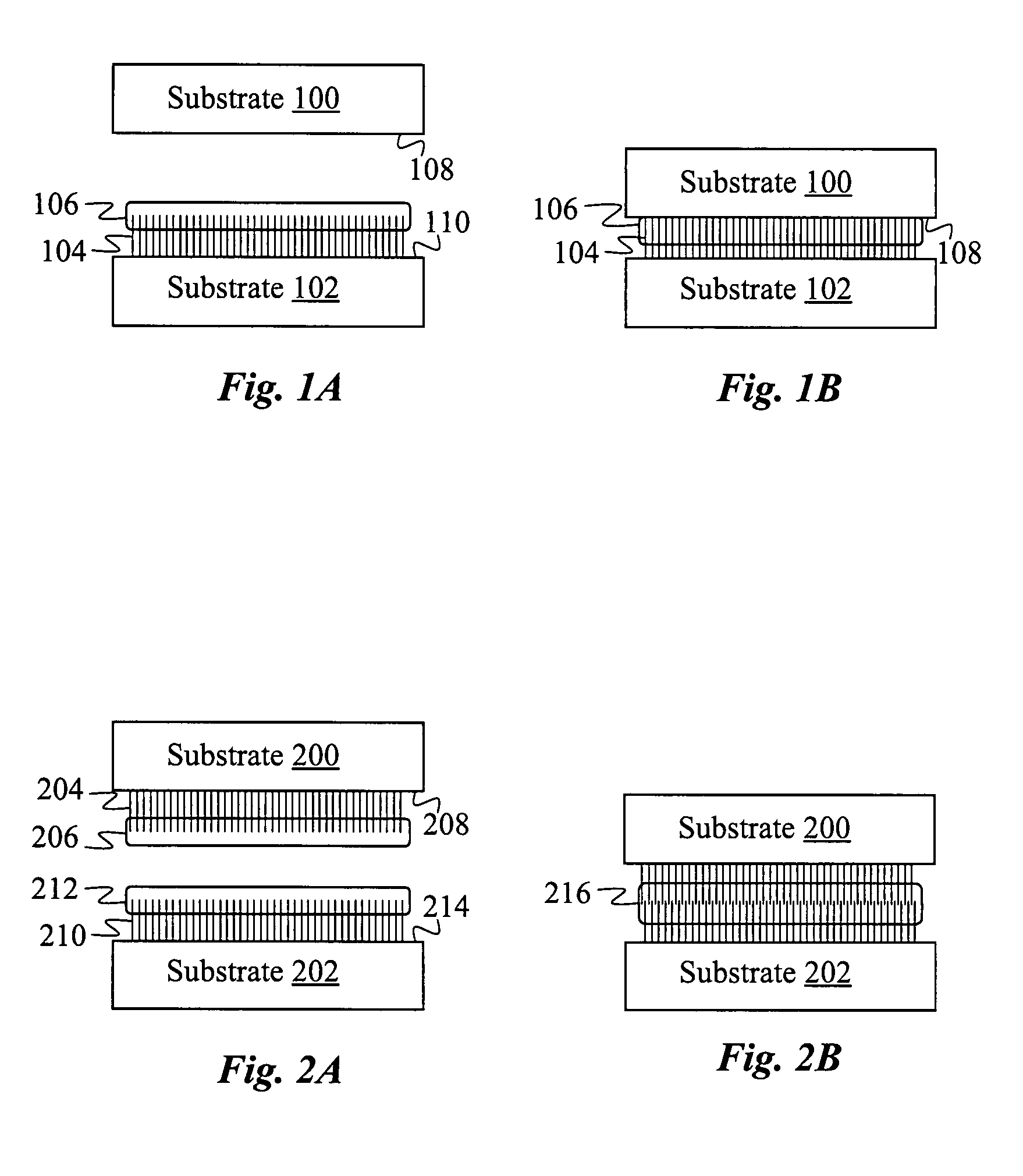
[0020]FIGS. 1A and 1B illustrate the formation of a composite thermal interface material from two substrates 100 and 102, a nanofiber film 104, and a binder 106, according to one embodiment of the invention. In typical applications, one of the substrates is a heat sink. As shown in FIG. 1A, substrate 100 initially has a bare exposed surface 108, while substrate 102 has the film of vertically aligned nanofibers 104 synthesized on its surface 110. Various well-known processes to synthesize nanofibers on substrates exist including deposition through arc discharge, laser ablation, and chemical vapor deposition (CVD). Typically in these processes, a catalysis layer less than a few nanometers thick is first deposited on the substrate (e.g., Si) to control and facilitate the nanofiber growth. The catalyst material is usually a metal oxide or metal such as iron, nickel, or cobalt. Annealing the catalyst layer at temperatures upwards of 800 C produces a monolayer of beads which become locali...


PUM

PropertyMeasurementUnit
Temperatureaaaaaaaaaa
Thicknessaaaaaaaaaa
Adhesion strengthaaaaaaaaaa

Abstract

A thermal interface material includes a mechanically compliant vertically aligned nanofiber film and a binder material for joining the nanofibers of the film to the surfaces of two substrates. Preferably, the binder material comprises a non-hydrocarbon-based material such as a metallic eutectic with a melting temperature below a nanofiber thermal damage threshold temperature of the film. The film is grown on a substrate which is then bonded to another substrate by the binder material in an adhesion process that may include pressure and heat. Alternatively, the film may be released from the substrate to produce a stand-alone thermal tape which may later be placed between two substrates and bonded.

Description

CROSS-REFERENCE TO RELATED APPLICATIONS[0001]This application claims priority from U.S. provisional patent application No. 60 / 834849 filed Jul. 31, 2006, which is incorporated herein by reference.FIELD OF THE INVENTION[0002]The present invention relates generally to thermal interface materials and methods for enhancing thermal dissipation from a heat source. More specifically, it relates to improved thermal interface materials comprising carbon nanotube films.BACKGROUND OF THE INVENTION[0003]A thermal interface material (TIM) used for dissipating heat to a heat sink or heat spreader preferably has a high intrinsic thermal conductivity. In addition, it is desirable that the TIM allows for high thermal conductivity at its contact with other materials. An effective TIM is typically mechanically compliant in order to optimize the area of contact. Examples of some known thermal interface materials include thermal greases, epoxy adhesives, and thermal gels such as silicones or olefins.[00...

Claims


Application Information

Patent Timeline
IPC IPC(8): B32B7/00B32B37/00
CPCB32B37/02Y10T428/24124B32B2309/02B32B2309/105B32B2311/00B32B2313/04B82Y10/00B82Y30/00H01L23/373H01L2924/0002B32B2038/0092Y10T428/14Y10T428/24132Y10T428/30Y10T428/24174H01L2924/00Y10T428/249927
Inventor PANZER, MATTHEWGOODSON, KENNETH E.HU, XUEJIAOMANN, DAVID
Owner THE BOARD OF TRUSTEES OF THE LELAND STANFORD JUNIOR UNIV
Why Eureka
Try Eureka