Anode for secondary battery, method of manufacturing it, and secondary battery

a secondary battery and anode technology, applied in the direction of non-aqueous electrolyte cells, cell components, electrochemical generators, etc., can solve the problems of reducing the characteristic of the charge and discharge cycle, the degree of expansion and shrinkage due to charge and discharge is large, and the ability to largely increase the capacity in the future. to achieve the effect of inhibiting the initial generation of irreversible capacity

Inactive Publication Date: 2009-03-12
SONY CORP
View PDF4 Cites 39 Cited by
  • Summary
  • Abstract
  • Description
  • Claims
  • Application Information

AI Technical Summary

Benefits of technology

[0017]However, the inventors have found the followings after their keen researches. Firstly, they found that non-crystallization provides different effect to inhibit generation of irreversible capacity according to each case, and amorphous structure silicon includes various types of silicon having different degree of local orderliness. Secondly, they found that non-crystallization effect varies according to the different degree of local orderliness, and as the degree of local orderliness of the amorphous silicon is lower, reversibility of the anode active material is more improved, and the charge and discharge cycle characteristics of the battery are more improved.
[0026]As described above, in the anode using silicon as the anode active material, a change in crystal structure due to charge and discharge cycle contributes to generation of irreversible capacity. Thus, it is effective to non-crystallize silicon in order to inhibit generation of irreversible capacity in the anode. However, as the inventors have found, it is not enough that the anode active material is just non-crystallized. Silicon having an amorphous structure includes various silicon having different degrees of local disorderliness. As the disorderliness degree is lower, the reversibility of the anode active material is further improved and the charge and discharge cycle characteristics of the battery are further improved. In the result, it is important to keep the degree of local disorderliness low as much as possible.
[0032]In the result, generation of irreversible capacity is prevented, for example, the lithium ion amount that is irreversibly inserted because of structural change due to charge and discharge cycle is small. In addition, superior charge and discharge cycle characteristics are realized, for example, the initial discharge capacity and the capacity retention ratio are large.
[0036]Further, according to the first and the second methods of manufacturing an anode for secondary battery of the embodiments of the invention, the degree of local orderliness in the amorphous silicon is controlled by specifying the deposition conditions. Thus, the first and the second anodes for secondary battery may be securely manufactured. Compared to a case that an anode for secondary battery is formed without specifying the deposition conditions, an anode for secondary battery having superior charge and discharge cycle characteristics may be securely manufactured.

Problems solved by technology

The battery capacity of the lithium ion secondary battery structured as above is close to the theoretical capacity, and it is hard to largely increase the capacity by improvement in the future.
However, in the case where silicon, tin and the like are used as an anode active material, the degree of expansion and shrinkage due to charge and discharge is large.
In the result, there is a disadvantage that the charge and discharge cycle characteristics are lowered.
However, in the anode using silicon, tin and the like as an anode active material, in addition to the foregoing structural break disadvantage, there is a disadvantage that the irreversible capacity ratio to the charge capacity in a charge and discharge cycle is larger than that in the anode using graphite as an anode active material.
That is, there is a disadvantage that the difference between the charge capacity and the discharge capacity therefrom obtained is large.
That is, part of lithium ions extracted from the cathode and inserted into the anode when charged is retained in the anode for some reason, and is not able to be returned back to the cathode when discharged.
Thus, it becomes difficult to achieve a design maximally using the battery capacity.
In the result, it is difficult to obtain sufficient charge and discharge cycle characteristics when the battery is actually used.
Thus, when the volume change is generated to the degree that each texture of each crystallite is not able to be maintained by lithium insertion when charged, stress strain is easily generated mainly in the vicinity of grain boundary connecting each crystallite.

Method used


Image

  • Anode for secondary battery, method of manufacturing it, and secondary battery
  • Anode for secondary battery, method of manufacturing it, and secondary battery
  • Anode for secondary battery, method of manufacturing it, and secondary battery

Examples


examples

[0114]Examples of the invention will be hereinafter described in detail. In the following description, the symbols used in the embodiment will be directly used accordingly.

examples 1 to 3

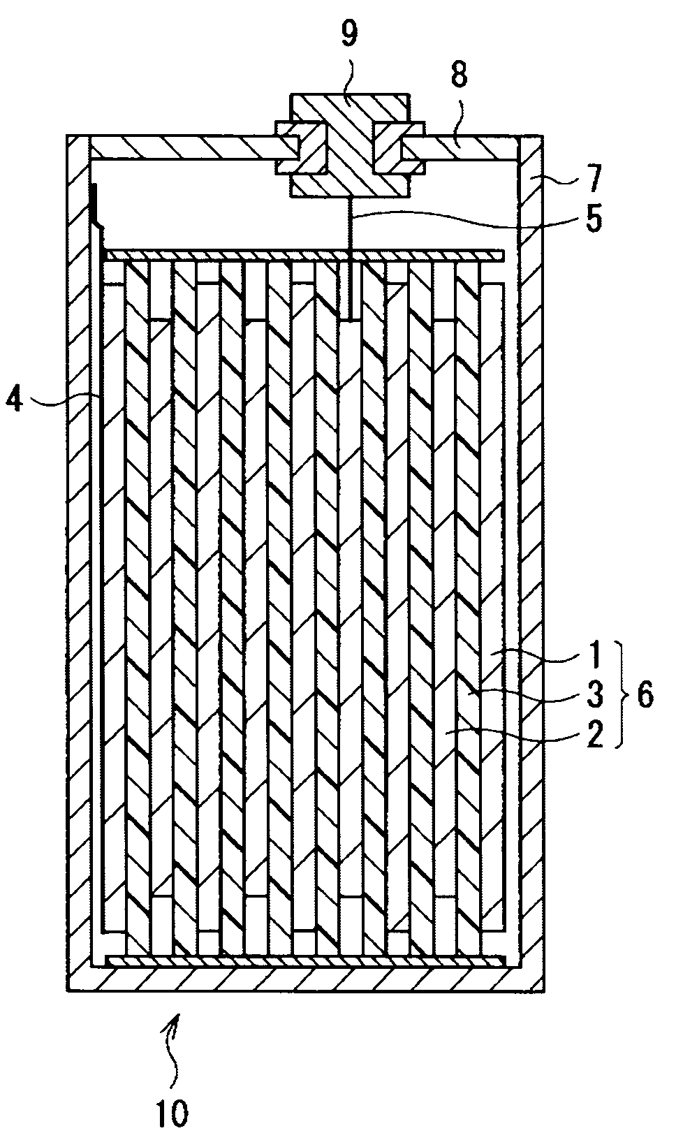
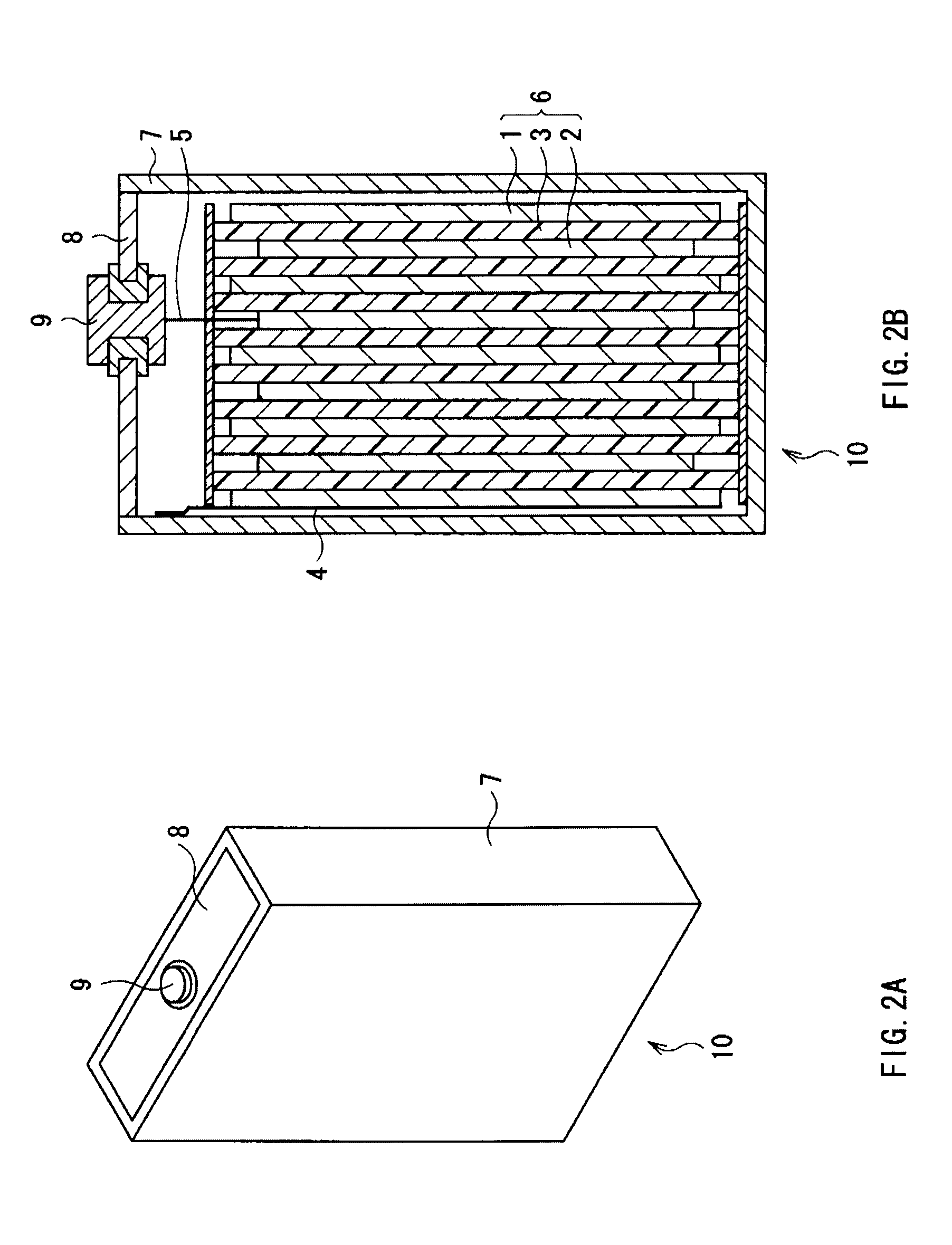
[0115]In these examples, the anode active material layer was formed on the anode current collector by vacuum evaporation method, the resultant was used as the anode 1, and thereby the square lithium ion secondary battery 10 shown in FIGS. 2A and 2B in the embodiment was fabricated. Then, the charge and discharge cycle characteristics were measured. A description will be specifically given.

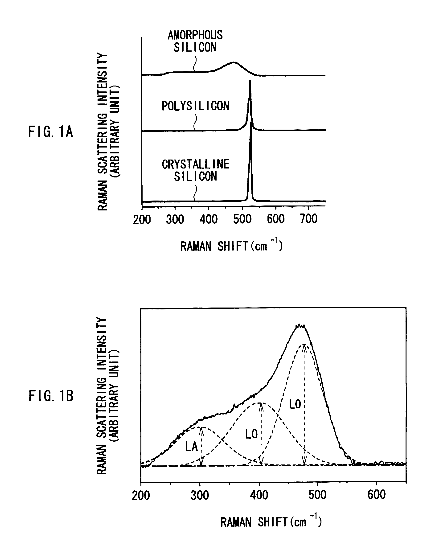
[0116]First, the anodes 1 that have amorphous silicon with various degree of local orderliness as the anode active material layer were formed as follows.

[0117]When the anode 1 was formed, as an electrode formation apparatus, the vacuum evaporation apparatus shown in FIG. 5 was used. As the anode current collector, a strip-shaped electrolytic copper foil having a thickness of 24 μm, the surface roughness value Rz of 2.5 μm, and the roughned both faces was used to form the anode 1. As an evaporation material, silicon single crystal was used. The deposition rate was from 50 to 100 nm / s. Then, the anod...

examples 4 to 9

[0140]In these examples, the lithium ion secondary batteries 10 were fabricated in the same manner as that of Examples 1 to 3, except that the anode active material layer was formed by sputtering method.

[0141]As an electrode formation apparatus, an opposed target type DC sputtering apparatus (not shown) was used to form the anode 1. As the anode current collector, a strip-shaped electrolytic copper foil having a thickness of 24 μm and the surface roughness value Rz of 2.5 μm with the roughned both faces was used. As an evaporation material, silicon single crystal was used. The deposition rate was 0.5 nm / s, and the anode active material layer being 5 to 6 μm thick was formed. The DC power was 1 kW, and argon was used as discharge gas. The anode active material layers having various degree of local orderliness were formed by adjusting deposition conditions such as the anode current collector temperature, the input electric power, and the gas pressure. In the opposed target type DC spu...


PUM

PropertyMeasurementUnit
temperatureaaaaaaaaaa

Abstract

An anode for secondary battery is provided with an anode active material layer containing silicon on an anode current collector. Silicon in the anode active material has an amorphous structure. In a Raman spectrum of silicon having the amorphous structure after an initial charge and discharge, 0.25≦LA / TO and / or 45≦LO / TO is satisfied, where an intensity of a scattering peak occurred in the vicinity of shift position 480 cm−1 based on scattering due to transverse optical phonon is TO, an intensity of a scattering peak occurred in the vicinity of shift position 300 cm−1 based on scattering due to longitudinal acoustic phonon is LA, and an intensity of a scattering peak occurred in the vicinity of shift position 400 cm−1 based on scattering due to longitudinal optical phonon is LO.

Description

CROSS REFERENCES TO RELATED APPLICATIONS[0001]The present invention contains subject matter related to Japanese Patent Application JP 2007-236646 filed in the Japanese Patent Office on Sep. 12, 2007, the entire contents of which being incorporated herein by reference.BACKGROUND OF THE INVENTION[0002]1. Field of the Invention[0003]The present invention relates to an anode for secondary battery suitable for lithium ion secondary batteries and the like and a method of manufacturing it, more specifically to an anode for secondary battery that generates a small amount of irreversible capacity, a method of manufacturing it, and a secondary battery using it.[0004]2. Description of the Related Art[0005]In recent years, high performance and multifunction of mobile devices have been developed. Accordingly, for secondary batteries used as a power source for the mobile devices, it is demanded to reduce their size, weight, and thickness and to achieve their high capacity.[0006]As a secondary bat...

Claims


Application Information

Patent Timeline
Patent Type & Authority Applications(United States)
IPC IPC(8): H01M10/26H01M4/36H01M4/04H01M4/40
CPCH01M4/134H01M4/38Y02E60/122H01M4/70H01M4/661Y02E60/10
Inventor KONISHIIKE, ISAMUKAWASE, KENICHI
Owner SONY CORP
Why Eureka
Try Eureka