Implantable graft assembly and aneurysm treatment

a technology of aneurysm and implanted grafts, applied in the field of medicine, can solve the problems of increased pressure on the brain, paralysis or coma of brain damage, fluid buildup, etc., and achieve the effect of limiting the flexibility of the implant and increasing the unexpanded profile of the implan

Inactive Publication Date: 2009-03-12
DESIGN & PERFORMANCE CYPRUS
View PDF31 Cites 71 Cited by
  • Summary
  • Abstract
  • Description
  • Claims
  • Application Information

AI Technical Summary

Benefits of technology

[0091]One of the greatest barriers to the use of covered stents and other graft-supporting expandable implants is that known grafts limit the flexibility of the implant and increase the unexpanded profile of the implant to a degree that makes deployment in the cerebrovascular implant difficult if not impossible. It has been found that a graft of serous tissue or membrane is strong enough, flexible enough and thin enough to overcome these problems. Thus, according to the tea

Problems solved by technology

Rupture of an aneurysm causes severe pain, internal hemorrhage, and, without prompt treatment, may result in death.
In addition the aneurysm may split, which may block vessels that branch from the vessel on which the aneurysm is located, or may release blood clots which block the flow of blood to other regions of the body.
Most cerebral aneurysms, however, result from a developmental abnormality of an arterial lining together with abnormal thinning of the arterial wall.
The bleeding may irritate, damage or destroy nearby brain cells, resulting in brain damage with paralysis or coma.
In severe cases, the bleeding may lead to death.
Blood from a ruptured aneurysm can block circulation of cerebrospinal fluid (CSF), leading to fluid buildup and increased pressure on the brain.
The bleeding may also lead to vasospasm, wherein the blood vessels of the brain narrow, such that insufficient blood is supplied to the brain, and a stroke may result.
A problem with using a covered stent to treat an aneurysm on such a bifurcated vessel is that the stent cover may partially or totally obstruct the entrance into the branch vessel, stopping flow into the branch vessel, increasing pressure at the bifurcation point and causing turbulent flow, factors that may lead to stenosis of the trunk vessel or of the branch vessel or damage to parts of the body dependent on blood from the branch vessel.
Such inva

Method used


Image

  • Implantable graft assembly and aneurysm treatment
  • Implantable graft assembly and aneurysm treatment
  • Implantable graft assembly and aneurysm treatment

Examples


first embodiment

[0164]a delivery system of the present invention including two guide wires where the orientation guide wire passes over the outside of a graft assembly is depicted in FIG. 5. In FIG. 5 is depicted the distal end of delivery catheter 90. Delivery catheter 90 is similar to that of prior art balloon catheters known in the art of stent delivery, and includes the distal end of a catheter guiding guide wire 66 running through a guide wire lumen 68 from the proximal end (not depicted) of guide wire lumen 68 out through the distal end of guide wire lumen 68 at the distal end of catheter 90. Graft assembly 76 including a graft 14 is crimped over a balloon 70, balloon 70 configured to function in the usual way. Unlike prior art stent-delivery catheters, delivery catheter 90 includes an additional orientation guide wire lumen that runs from the proximal end of delivery catheter 90 (not depicted) to an orientation guide wire port 94 that is positioned proximally to balloon 70. In FIG. 5, an ori...

second embodiment

[0166]a delivery system of the present invention including two guide wires where an orientation guide wire 92 passes between a delivery catheter 96 and a graft assembly 76 to emerge through an alignment hole 102 reinforced with gold grommet 104 penetrating through a graft 14 of graft assembly 76 is depicted in FIGS. 6A and 6B. FIGS. 6A and 6B depict the distal end of delivery catheter 96. Delivery catheter 96 is similar to that of prior art balloon catheters known in the art of stent delivery, and includes the distal end of a catheter guiding guide wire 66 running through a guide wire lumen 68 inside a main catheter shaft 98 from the proximal end (not depicted) of guide wire lumen 68 out through the distal end of guide wire lumen 68 at the distal end of delivery catheter 96. Graft assembly 76 including a graft 14 is crimped over a balloon 70, balloon 70 configured to function in the usual way.

[0167]Unlike prior art stent-delivery catheters, delivery catheter 96 includes an additiona...


PUM


Abstract

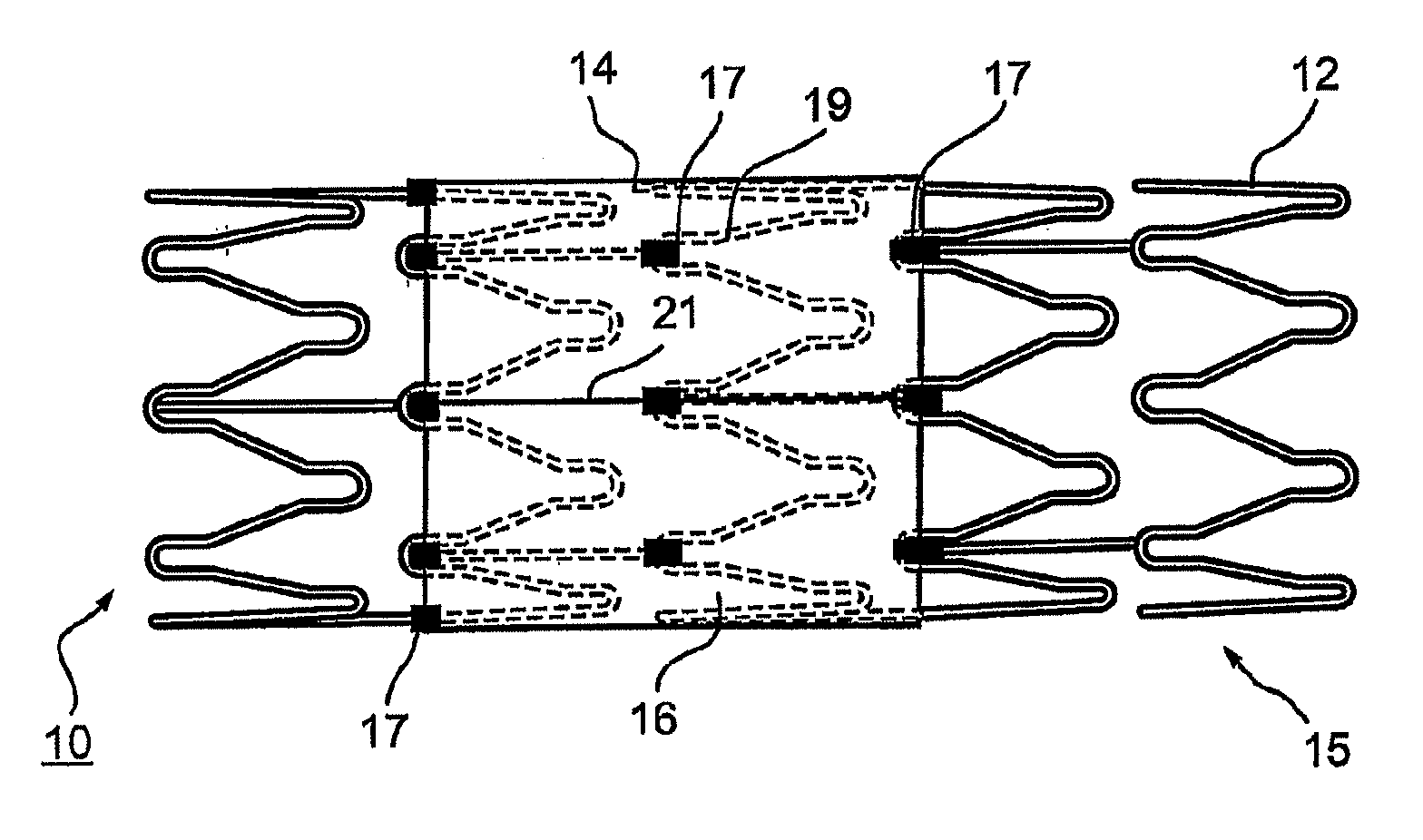
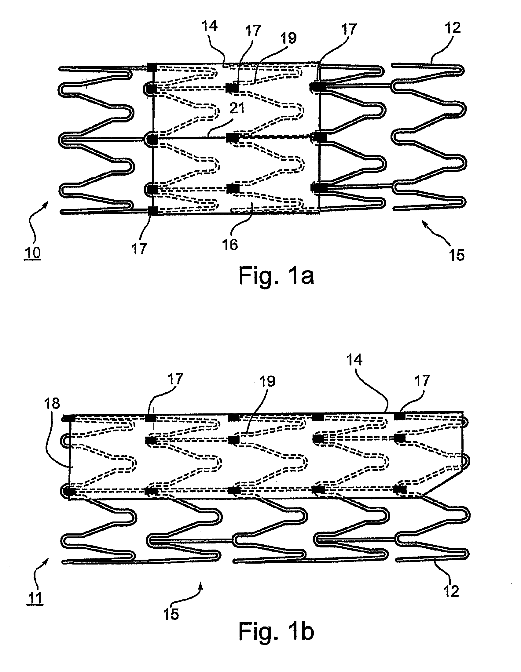
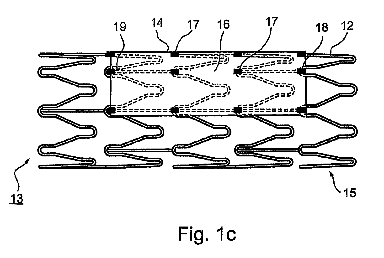
Disclosed is an implantable graft assembly comprising a graft secured to a expandable tubular frame, the graft only partially covering the frame and the use of the graft assembly in treating an aneurysm, especially a cerebral aneurysm. Disclosed is also a method of treating an aneurysm by deploying an implantable graft assembly. Disclosed is also the use of serous tissue for the preparation of a cerebrovascular implant, especially as a graft, especially as a component of a cerebrovascular implantable graft assembly.

Description

FIELD AND BACKGROUND OF THE INVENTION[0001]The present invention relates to the field of medicine, and more particularly to the field of intracorporeal implantable devices especially implantable graft assemblies. The present invention also relates to the treatments of aneurysms, especially cerebral aneurysms and aneurysms of bifurcated vessels.[0002]An aneurysm is a localized ballooning of a blood vessel by more than 50% of the diameter of the vessel. Aneurysms can occur in any blood vessel, although they are most common in arteries, particularly in the arteries at the base of the brain (the Circle of Willis) and in the aorta. Approximately 85% of cerebral aneurysms develop in the anterior part of the Circle of Willis and involve the internal carotid arteries and major branches thereof. The most common sites include the anterior communicating artery (30-35%), the bifurcation of the internal carotid and posterior communicating artery (30-35%), the bifurcation of the middle cerebral a...

Claims


Application Information

Patent Timeline
IPC IPC(8): A61F2/06A61F2/82
CPCA61B17/12022A61B17/12118A61B2017/1205A61F2/07A61F2250/0008A61F2/95A61F2002/075A61F2002/823A61F2/915A61F2/91A61F2/86A61F2/90
Inventor VONDERWALDE, CARLOSGONZALEZ-RESENDIZ, CARLOS
Owner DESIGN & PERFORMANCE CYPRUS
Why Eureka
Try Eureka