Test Apparatus

a technology of test apparatus and test tube, which is applied in the direction of material analysis using wave/particle radiation, instruments, nuclear engineering, etc., to achieve the effects of reducing transfer time, high speed, and large capacity

Active Publication Date: 2009-03-19
HITACHI HIGH-TECH CORP
View PDF1 Cites 1 Cited by
  • Summary
  • Abstract
  • Description
  • Claims
  • Application Information

AI Technical Summary

Benefits of technology

[0014]The present invention further provides a test apparatus using an electron beam, in which the scan control unit has a small-capacity transformation table (LUT) having a capacity equivalent to image size and transforming the X and Y scan coordinates, and a transformation table (LUT) as a storage of a large capacity which is equal to that of plural image sizes and which stores transformation data by scan types to address plural scan types. During a scan operation, coordinate transformation is performed at high speed using the small-capacity transformation table. During a scan stops, the transformation data is transferred from the large-capacity transformation table (LUT) to the small-capacity transformation table (LUT). Consequently, the test apparatus is compatible with the plural scan types, can transform coordinates to arbitrary coordinates, and can perform a high-speed scan control.
[0015]The present invention further provides a test apparatus using an electron beam, in which the scan control unit has, as the small-capacity transformation table (LUT), two or more first small-capacity transformation tables (LUTs) and two or more second small-capacity transformation tables (LUTs) for X and Y coordinates. During a scan operation, coordinate transformation is performed with the first small-capacity transformation tables (LUTs) and, simultaneously, the transformation data is transferred from the large-capacity transformation table (LUT) to the second small-capacity transformation tables (LUTs). After completion of the scan, input / output signals of the first small-capacity transformation tables (LUTs) and those of the second small-capacity transformation tables are switched, and the two or more small-capacity transformation tables (LUT) are alternately used per scan. In such a manner, transformation data for the next scan is transferred from the large-capacity transformation table to the small-capacity transformation table. By reduction in transfer time, the throughput is improved.
[0016]The present invention further provides a test apparatus using an electron beam, further including a sorting unit that sorts image data scanned in an arbitrary direction to an order of a scan in a normal predetermined direction on the basis of the scan coordinates generated by the scan control unit. The sorting unit has a sorting memory having a capacity equal to that of image data, a memory control unit for writing data to the sorting memory using the scan coordinates as a memory address, and an image range detecting unit for detecting an image computation range from the scan coordinates. The sorting unit transfers the image data to the image computing unit per image computation range, thereby performing high-speed sorting and transfer.

Problems solved by technology

A test apparatus that obtains an image by using an electron beam has a problem of the influence of a charge-up phenomenon.

Method used


Image

  • Test Apparatus
  • Test Apparatus
  • Test Apparatus

Examples


first embodiment

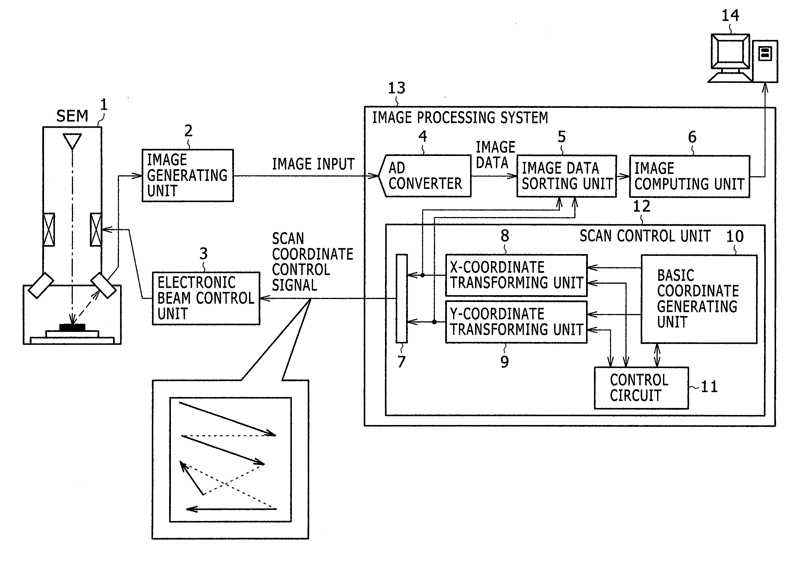
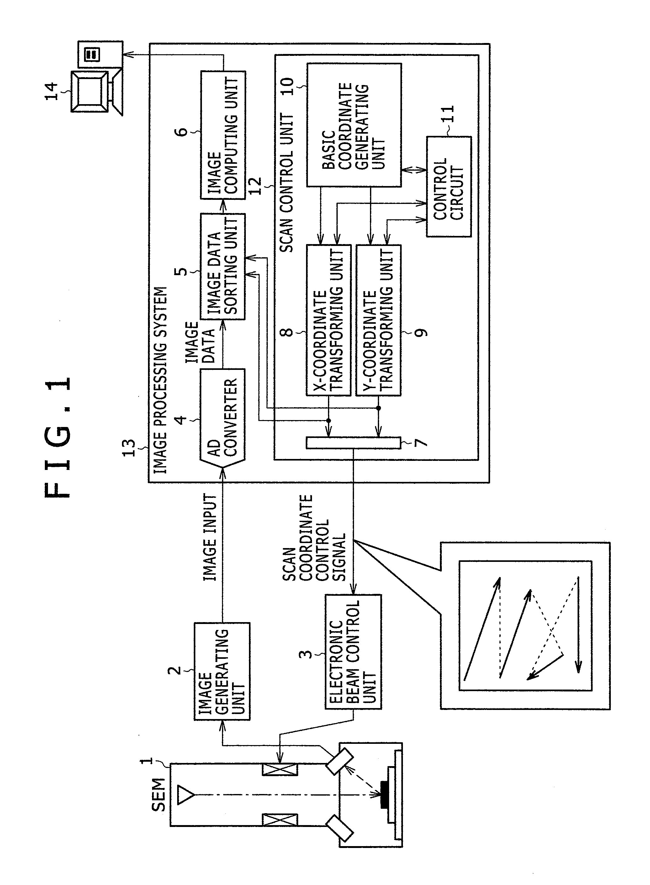
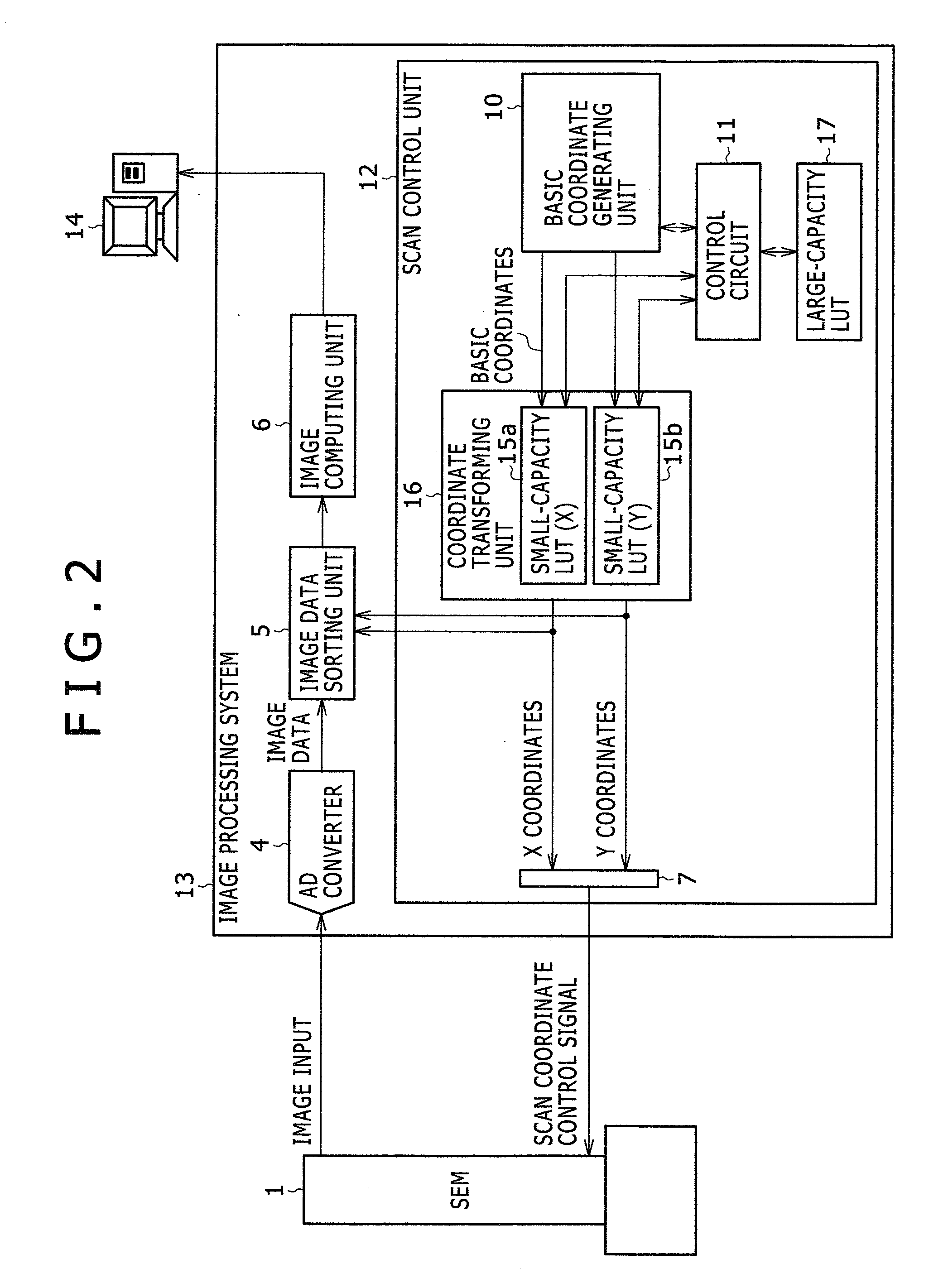
[0039]FIG. 2 is a diagram showing the configuration of the first embodiment. In the embodiment, as the X-coordinate transforming unit 8 and the Y-coordinate transforming unit 9 shown in FIG. 1, small-capacity transformation tables (LUTs) 15a and 15b for transformation to X and Y scan coordinates at high speed and a large-capacity transformation table (LUT) 17 having a capacity of plural image sizes and storing transformed data by scan types so as to be adapted to plural scan types are used. The X and Y coordinates are transformed by pre-storing data to be transformed in the transformation tables (LUTs). The transformation tables (LUTs) are a memory (storing unit). The transform data is stored in the memory. The basic coordinates generated by the basic coordinate generating unit 10 are used as an address in the memory. By reading data stored in the address, coordinate transformation is performed and X·Y scan coordinates are obtained. It should be noted that the image generating unit ...

second embodiment

[0045]FIG. 3 is a diagram showing the configuration of a second embodiment of the scan control unit in the image processing system. In the second embodiment, a coordinate transforming unit 16 in FIG. 2 has two or more transformation tables (LUTs) for each of the X and Y coordinates. In the configuration, during a scan operation, coordinate transformation is performed with the first small-capacity transformation table (X1 or Y1) 15a or 15b. Simultaneously, transformation data is transferred from the large-capacity transformation table 17 to the second small-capacity transformation table (X2 or Y2) 15c or 15d. After completion of the scan, input / output signals of the first small-capacity transformation table (X1 or Y1) 15a or 15b and those of the second small-capacity transformation table (X2 or Y2) 15c or 15d are switched by switching units 18a, 19a, 18b, and 19b. In such a manner, the two small-capacity transformation tables are alternately used per scan.

[0046]With the configuration...


PUM

PropertyMeasurementUnit
scanning electronic microscopeaaaaaaaaaa
sizesaaaaaaaaaa
speedaaaaaaaaaa

Abstract

A scan control unit for generating two-dimensional coordinates for performing a scan with an electron beam of an electron scanning microscope is provided with first and second transforming units for transforming coordinates in the horizontal (X) direction and the vertical (V) direction. An area to be tested in a sample is scanned with an electron beam in an arbitrary direction. As the first and second transforming units, small-capacity transformation tables (LUTs) capable of operating at high speed in each of the horizontal (X) direction and the vertical (Y) direction are used. By also using a large-capacity transformation table (LUT) that stores coordinate transformation data corresponding to plural scan types, a test apparatus compatible with the plural scan types, having multiple functions, and capable of performing high-speed scan control is realized.

Description

CLAIM OF PRIORITY[0001]The present application claims priority from Japanese patent application JP 2007-237988 filed on Sep. 13, 2007, the content of which is hereby incorporated by reference into this application.BACKGROUND OF THE INVENTION[0002]The present invention relates to a test apparatus for testing a semiconductor device, a substrate, a photomask (exposure mask), a liquid crystal, and the like having a fine pattern.[0003]In recent years, as semiconductor integrated circuits are becoming finer and having higher integration, a pattern on semiconductor wafer is tested at the end of each of manufacturing processes of the semiconductor integrated circuits in order to detect, early or in advance, occurrence of an abnormality and a failure in the manufacturing processes. Test methods and apparatuses to detect a defect are being practically used. In the test apparatuses, a test is conducted by obtaining image information of an area to be tested with a scanning electron microscope (...

Claims


Application Information

Patent Timeline
Patent Type & Authority Applications(United States)
IPC IPC(8): G01N23/00
CPCG01N23/2251H01J2237/2817H01J2237/221
Inventor HIRANO, KATSUNORITOBA, TADANOBUOHASHI, MASAHIROWADA, MASASHI
Owner HITACHI HIGH-TECH CORP
Why Eureka
Try Eureka